Winding device of electromagnetic switch coil

A technology for electromagnetic switches and winding equipment, applied in electrical switches, coil manufacturing, circuits, etc., can solve problems such as inability to adjust, high operator proficiency requirements, and inability to adjust the tension of the coil, and achieve the effect of improving efficiency.

Inactive Publication Date: 2016-07-20
常州市武进亚太机电配件有限公司
View PDF0 Cites 1 Cited by
  • Summary
  • Abstract
  • Description
  • Claims
  • Application Information

AI Technical Summary

Problems solved by technology

[0002] At present, there are generally two ways to wind the electromagnetic switch coil: the first is the traditional manual winding, which has low efficiency and requires high proficiency of the operator.
The second is to use the winding machine to automatically wind the wires, so that the density of the coil windings can be controlled, but the existing winding machines have two defects: (1) they are all single wire coils, and the winding efficiency is limited; (2) The tension of the reel cannot be adjusted and cannot be adjusted according to the actual situation

Method used


Image

  • Winding device of electromagnetic switch coil
  • Winding device of electromagnetic switch coil

Examples


Embodiment 1

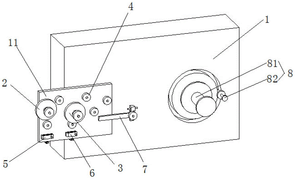
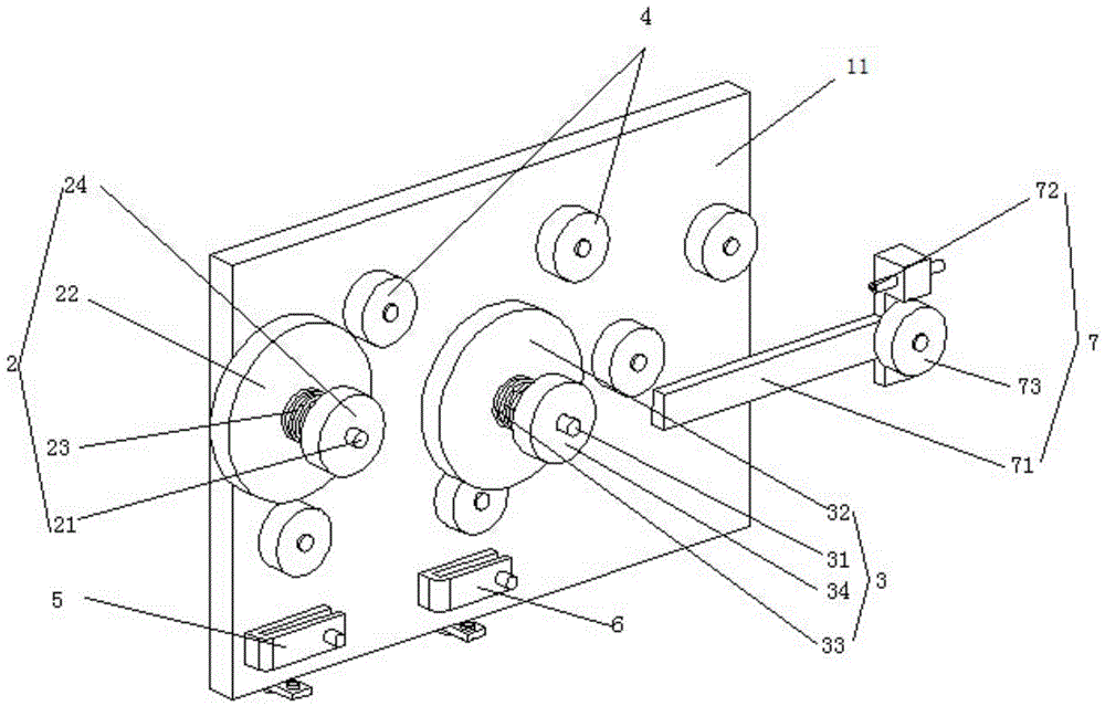
[0022] See figure 1 and figure 2 , the electromagnetic switch coil winding equipment of the present embodiment includes a frame 1; also includes a first wire routing wheel 2, a second wire routing wheel 3, a plurality of guide wheels 4, and a first upper wire slot arranged on the frame 1 5. The second upper wire slot 6, the parallel assembly 7 and the winding frame 8; the centers of the first wire routing wheel 2 and the second wire routing wheel 3 are not on the same horizontal line; the first upper wire slot 5 and the second upper wire slot 6 They are respectively arranged under the first line wheel 2 and the second line wheel 3; the parallel assembly 7 includes a parallel frame 71, a wire conduit 72 and a guide wheel 73; one end of the parallel frame 71 is fixed on the frame 1 , the other end stretches out from the frame 1; the wire tube 72 and the wire wheel 73 are arranged up and down on the end of the parallel horizontal frame 71 extending out of the frame 1; the windi...


PUM


Abstract

The invention discloses a winding device of an electromagnetic switch coil. The device comprises a rack, and a first wire routing wheel, a second wire routing wheel, multiple guide wheels, a first wire mounting slot, a second wire mounting slot, a wire combining assembly and a winding rack which are arranged on the rack. The circle centers of the first wire routing wheel and the second wire routing wheel are not located on the same horizontal line. The first wire mounting slot and the second wire mounting slot are arranged under the first wire routing wheel and the second wire routing wheel. The wire combining assembly comprises a wire combining crossarm, a wire conduit and a wire guide wheel. One end of the wire combining crossarm is fixed on the rack, and the other end stretches out of the rack. The wire conduit and the wire guide wheel are arranged in an up and down mode and are arranged on the end, stretching out of the rack, of the wire combining crossarm. The winding rack comprises a coil shaft and an insulation tape frame. The winding rack comprises a coil shaft, an insulation tape frame and a tape pressing mechanism. The tape pressing mechanism is arranged beside the coil shaft and is used for compressing an insulation tape winded on the coil. According to the device, through arranging the two wire routing wheels, the efficiency can be doubled.

Description

technical field [0001] The invention relates to an electromagnetic switch coil winding device. Background technique [0002] At present, there are generally two ways to wind the coil of the electromagnetic switch: the first is the traditional manual winding, which has low efficiency and requires high proficiency of the operator. The second is to use the winding machine to automatically wind the wires, so that the density of the coil windings can be controlled, but the existing winding machines have two defects: (1) they are all single wire coils, and the winding efficiency is limited; (2) The tension of the wire reel cannot be adjusted and cannot be adjusted according to the actual situation. Contents of the invention [0003] The object of the present invention is to solve the aforementioned technical problems and provide a high-efficiency electromagnetic switch coil winding device. [0004] The technical solution for realizing the purpose of the present invention is an...

Claims


Application Information

Patent Timeline
IPC IPC(8): H01F41/06B65H54/44H01H11/00
Inventor 李文玉
Owner 常州市武进亚太机电配件有限公司
Why Eureka
Try Eureka