
High density electrical resistivity imaging method

A high-density resistivity, imaging method technology, applied in the field of imaging, can solve the problems of lack of quantitative conversion, lack of performance, lack of deep coupling, etc., to achieve the effect of saving calculation time, strong applicability, and improving the accuracy of resistivity imaging

Inactive Publication Date: 2016-07-20
ZHEJIANG UNIV OF WATER RESOURCES & ELECTRIC POWER
View PDF6 Cites 7 Cited by
  • Summary
  • Abstract
  • Description
  • Claims
  • Application Information

AI Technical Summary

Problems solved by technology

Its joint use with resistivity data has been proved to be the best means to detect topographic water flow and seawater intrusion, etc., but at present, the two are still combined in a loose form for joint detection, without deep coupling and lack of quantitative conversion, thus not realizing the value of its application

Method used


Image

  • High density electrical resistivity imaging method

Examples


Embodiment Construction

[0015] The following will clearly and completely describe the technical solutions in the embodiments of the present invention with reference to the accompanying drawings in the embodiments of the present invention. Obviously, the described embodiments are only some, not all, embodiments of the present invention. Based on the embodiments of the present invention, all other embodiments obtained by persons of ordinary skill in the art without making creative efforts belong to the protection scope of the present invention.

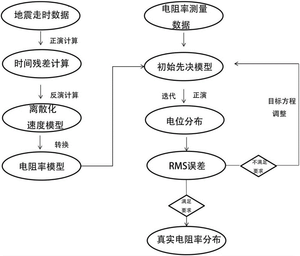
[0016] see figure 1 , in an embodiment of the present invention, a high-density resistivity imaging method includes the following steps: (1). For the survey area, establish a suitable grid profile according to the terrain characteristics and the needs of high-density resistivity measurement and artificial refraction seismic measurement Sub-plan; (2). According to grid division, establish an inversion model of artificial refraction seismic data for inversion ca...


PUM


Abstract

The invention discloses a high density electrical resistivity imaging method, comprising following steps: establishing a suitable mesh subdivision scheme aiming at a detection area according to topographic features and the requirement of high density electrical resistivity measurement and artificial refraction seismic survey; establishing an artificial refraction seismic data inversion model to perform inversion calculation to obtain a discrete velocity module; converting the discrete velocity module into a discrete electrical resistivity module according to the empirical equation between the velocity and the resistivity; using the obtained resistivity module as a constrained initial module of resistivity inversion to perform inversion calculation. By means of the method which is a novel technology for greatly increasing the electrical resistivity imaging precision, the electrical resistivity data and the artificial refraction seismic data are fused with each other; the processed artificial refraction seismic data is used as a prerequisite of electric resistivity imaging to perform constrained inversion calculation so that calculation time can be greatly saved under same hardware conditions and imaging precision is increased.

Description

technical field [0001] The invention relates to an imaging method, in particular to a high-density resistivity imaging method. Background technique [0002] Resistivity imaging (ERT) technology is an imaging technology that uses the potential or potential difference generated by the electric field excited by the point power source measured around the exploration area to study the resistivity distribution of the underground medium in the exploration area. The high-density resistivity imaging method is to arrange many electrodes on the measuring line at the same time, and realize the automatic combination of various devices and different pole distances in the resistivity method through the control of the automatic electrode switch, so that the electrodes can be measured at one time. A method for multiple apparent resistivity parameters under multiple devices and multiple pole distances. In recent years, with the development of computer technology, high-density resistivity ima...

Claims


Application Information

Patent Timeline
IPC IPC(8): G01V11/00
CPCG01V11/00Y02A90/30
Inventor 卢德宝王凤陈晓东欧健
Owner ZHEJIANG UNIV OF WATER RESOURCES & ELECTRIC POWER
Learn More