
Ultrasonic Measuring System, Means Of Transportation And Method For Operating An Ultrasonic Transmitter-receiver Device

A receiving device, ultrasonic measurement technology, applied in the direction of measuring device, radio wave measurement system, sound wave re-radiation, etc., can solve problems such as low anti-interference, limited measurement update rate, detection robustness limit, etc., to improve detection safety sexual effect

Active Publication Date: 2016-07-20
ROBERT BOSCH GMBH
View PDF8 Cites 0 Cited by
  • Summary
  • Abstract
  • Description
  • Claims
  • Application Information

AI Technical Summary

Problems solved by technology

This limits the system's measurement update rate (measurement cycles per unit of time) in today's systems, since typically four front or rear sensors have overlapping "visible areas" or detection areas and thus cannot be performed simultaneously in one measurement cycle. send
In addition, the use of only one fixed operating frequency results in limitations in the robustness of the detection, for example due to low interference immunity with respect to ultrasonic signals of other vehicles

Method used


Image

  • Ultrasonic Measuring System, Means Of Transportation And Method For Operating An Ultrasonic Transmitter-receiver Device
  • Ultrasonic Measuring System, Means Of Transportation And Method For Operating An Ultrasonic Transmitter-receiver Device
  • Ultrasonic Measuring System, Means Of Transportation And Method For Operating An Ultrasonic Transmitter-receiver Device

Examples


Embodiment Construction

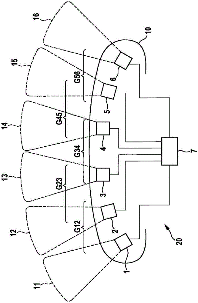
[0029] figure 1 A schematic top view of an exemplary embodiment of an ultrasonic measuring system 20 according to the invention with ultrasonic sensors 1 , 2 , 3 , 4 , 5 , 6 in the bumper of a car 10 as kinematics is shown. . The ultrasound sensors 1 , 2 , 3 , 4 , 5 , 6 have corresponding transmission lobes 11 , 12 , 13 , 14 , 15 , 16 . The ultrasonic sensors 1 , 2 , 3 , 4 , 5 , 6 are respectively connected via signal lines to a central control unit 7 as an analysis and processing unit. Depending on the surrounding objects, the ultrasonic sensors 1 , 2 , 3 , 4 , 5 , 6 are only capable of receiving cross-echoes from each other only conditionally. By way of example, the ultrasonic sensors 1 , 2 , 3 , 4 , 5 , 6 are divided into groups G12 , G23 , G34 , G45 , G56 in order to be able to take into account the possibility or impossibility of cross echoes. For example, groups G12 and G45 are arranged so far apart from one another that an echo based on the signal of group G45 cannot...


PUM


Abstract

The invention discloses an ultrasonic measuring system, means of transportation and method for operating an ultrasonic transmitter-receiver device. The method includes that an ultrasonic transmitter-receiver emits a first signal representing a code word from a first ultrasonic sensor and a second signal from a second ultrasonic sensor as part of a measuring cycle. Both sensors belong to the same group of ultrasonic sensors. A third ultrasonic sensor receives echoes from the two signals and distinguishes components from the first signal and the second signal of the echoes by decoding the codeword.

Description

technical field [0001] The invention relates to an ultrasonic measuring system, a kinematic mechanism and a method for operating an ultrasonic transceiver for a kinematic mechanism. The invention also relates, inter alia, to improvements in signal recognition and preprocessing by means of coding. Background technique [0002] The use of ultrasonic transmitter-receivers ("ultrasonic sensors" for short) in automotive engineering has been known for many years for environment detection and distance measurement. Driver assistance functions are likewise often based on ultrasonic sensors, which are usually arranged in groups of 4 to 6 per bumper on the kinematics (hereinafter “vehicle” for the sake of simplicity). [0003] DE 10 2008 007 667 A1 discloses a method for operating a parking assistance system, in which ultrasound-based distance sensors are activated in two different modes with temporally different transmission sequences. In particular for the transition it is proposed...

Claims


Application Information

Patent Timeline
Patent Type & Authority Applications(China)
IPC IPC(8): G01S15/87G01S15/93G01S15/10G01S15/931
CPCG01S15/10G01S15/87G01S15/93G01S15/102G01S15/104G01S15/931G01S7/52G01S15/878
Inventor A·克洛茨T·赖纳M·舒曼
Owner ROBERT BOSCH GMBH
Learn More