
A brake beam fatigue test bench

A technology of fatigue test and braking beam, which is applied in the field of fatigue test bench, can solve the problems of large space occupied by the test bench, low test efficiency, difficult adjustment, etc., and achieve the goal of increasing the test loading frequency, improving the test efficiency, and improving the fatigue life Effect

Inactive Publication Date: 2019-02-12
CRRC QINGDAO SIFANG ROLLING STOCK RES INST
View PDF5 Cites 0 Cited by
  • Summary
  • Abstract
  • Description
  • Claims
  • Application Information

AI Technical Summary

Problems solved by technology

[0004] At present, there are three types of existing brake beam fatigue test benches. One is the horizontal installation of the brake beam. The fatigue test of one brake beam is low in test efficiency; the second is the horizontal placement of the brake beam, which can test two brake beams at the same time, using a lateral actuator to apply a pressure load, and a vertical actuator Tangential load is applied, but this kind of test bench occupies a large space, and the test bench needs to apply loads separately in the lateral and vertical directions. The third type is the gantry form. The brake beam of this type is placed vertically, and two brake beams can be tested at the same time. Both the pressure load and the tangential load are applied by the vertical actuator. The structural rigidity is too small, and there will be large deformation during the loading process of the fatigue test, which will affect the increase of the test loading frequency and the improvement of the test efficiency. At present, the maximum test loading frequency is 2.3HZ; Fatigue cracks are easy to appear; the gap between the test bench and the brake beam under test is too large and difficult to adjust

Method used


Image

  • A brake beam fatigue test bench
  • A brake beam fatigue test bench
  • A brake beam fatigue test bench

Examples


Embodiment Construction

[0030] In the following, the present invention will be specifically described through exemplary embodiments. It should be understood, however, that elements, structures and characteristics of one embodiment may be beneficially incorporated in other embodiments without further recitation.

[0031] In the description of the present invention, it should be noted that the orientation or positional relationship indicated by the terms "upper", "lower", "front", "rear", "top" and "bottom" in the brake beam fatigue test rig is Based on the positional relationship shown in the drawings, it is only for the convenience of describing the present invention and simplifying the description, rather than indicating or implying that the referred device or element must have a specific orientation, be constructed and operated in a specific orientation, and therefore cannot be construed as a Invention Limitations. In addition, the terms "first", "second", and "third" are used for descriptive purp...


PUM


Abstract

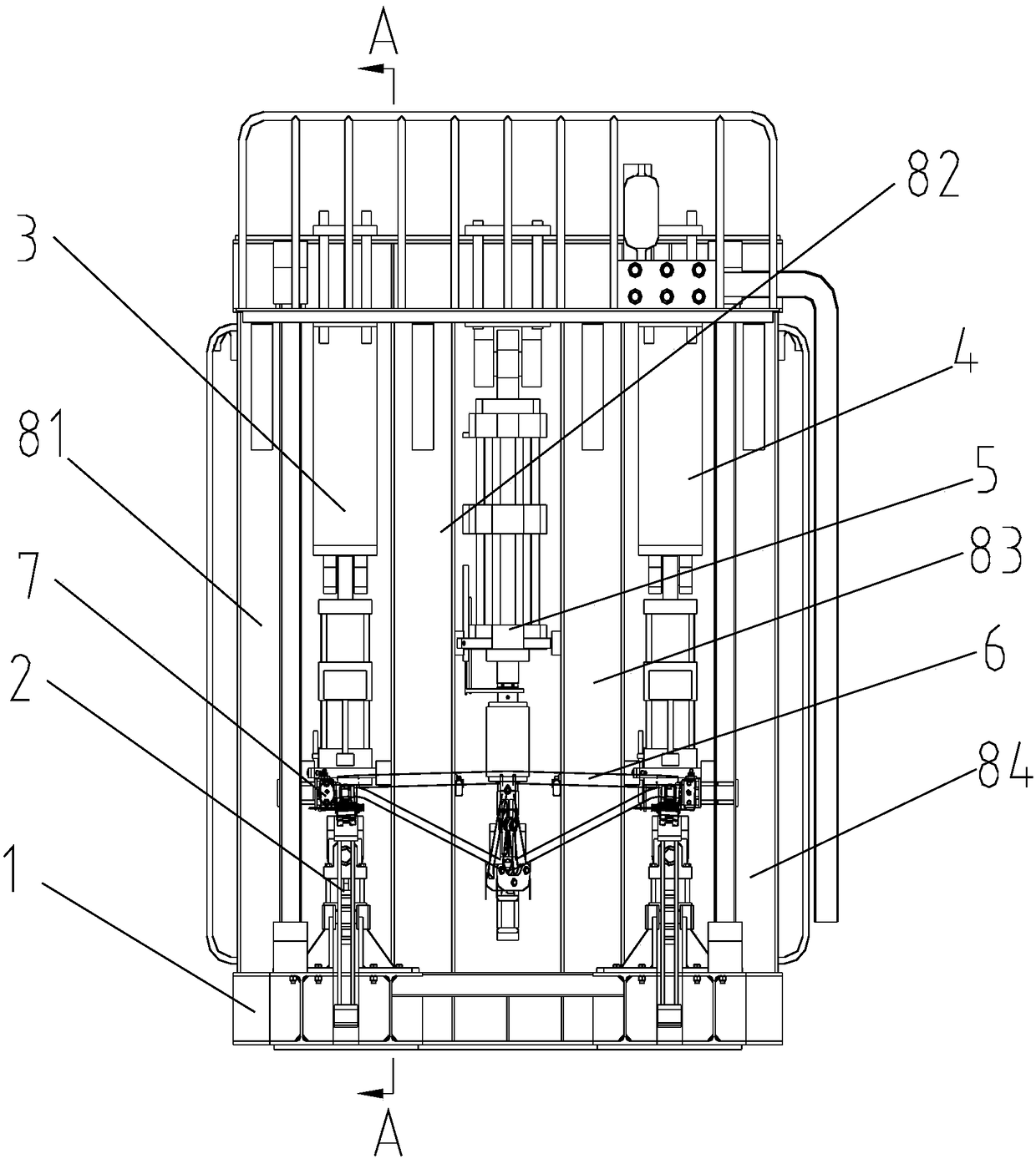
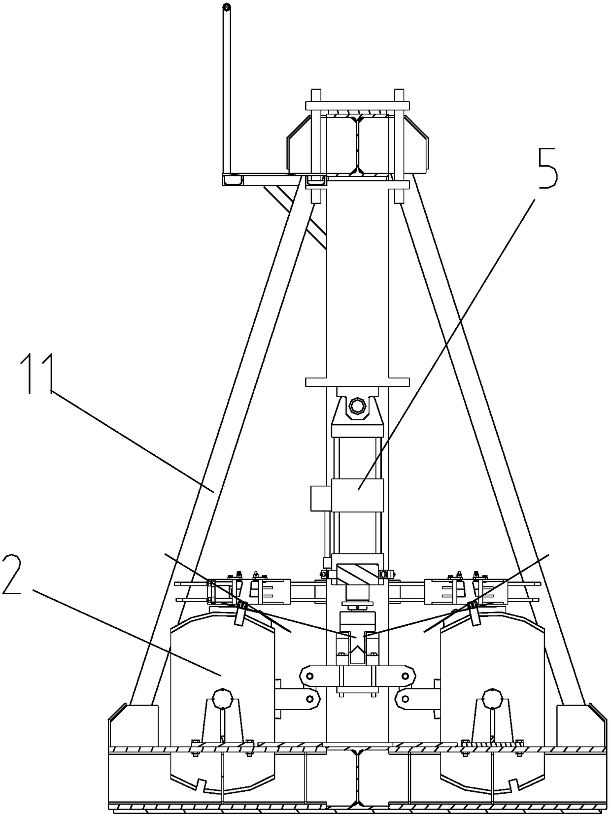
The invention provides a brake beam fatigue test stand which is used for testing fatigue strength of two brake beams simultaneously. The test stand comprises a pedestal and four upright columns which are perpendicular to the pedestal and arranged on the pedestal with intervals; a first tangential force load actuator is vertically installed between the first upright column and the second upright column; the front side and the rear side of the first tangential force load actuator are provided with simulation wheels; a pressure load actuator is installed vertically between the second upright column and the third upright column; a second tangential force load actuator is vertically installed between the third upright column and the fourth upright column; the front side and the rear side of the second tangential force load actuator are provided with simulation wheels; the second tangential force load actuator and the first tangential force load actuator are symmetrically arranged with the pressure load actuator being as a symmetric center; two brake beams are vertically installed at the front side and the rear side of the upright columns; two ends of the brake beams are supported on the simulation wheel tread surfaces. By means of the brake beam fatigue test stand, the vertical and transverse stiffness of test stand are increased.

Description

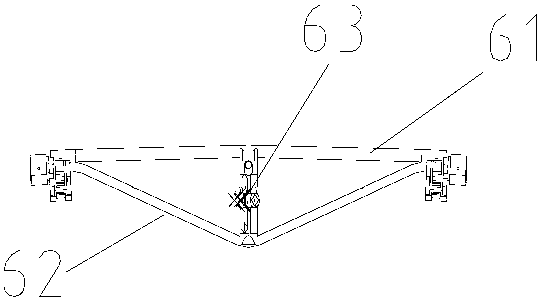
technical field [0001] The invention belongs to the technical field of rail transit, and in particular relates to a fatigue test bench for a brake beam of a railway freight car. Background technique [0002] The railway freight car brake beam is the most important part of the railway freight car foundation braking device. When the vehicle performs braking operation, the brake beam can transmit the braking force generated by the brake cylinder to the brake shoe, and then realize the vehicle braking. Such as figure 1 Shown is a schematic diagram of the structure of the brake beam. The brake beam 6 is a triangular beam, which includes a horizontal bar 61 and a slanting bar 62 arranged at both ends of the bar 61 . Beam pillars 63 are vertically arranged between them, and the installation direction of the brake beam is horizontal during normal use. [0003] In order to ensure the reliability of the brake beam, it is necessary to perform a fatigue test on it. When the brake bea...

Claims


Application Information

Patent Timeline
Patent Type & Authority Patents(China)
IPC IPC(8): G01M17/08
CPCG01M17/08
Inventor 金星罗运康
Owner CRRC QINGDAO SIFANG ROLLING STOCK RES INST
Learn More