
A Measuring Device for Average Corrosion Depth in X-ray Stress Test

A stress test and corrosion depth technology, applied in mechanical depth measurement and other directions, can solve the problems of affecting the accuracy of residual stress on the surface of objects, uneven corrosion pits, large measurement errors, etc., to improve test stability, improve work efficiency, and ensure self-balancing effect

Active Publication Date: 2019-03-19
武汉钢铁有限公司
View PDF5 Cites 0 Cited by
  • Summary
  • Abstract
  • Description
  • Claims
  • Application Information

AI Technical Summary

Problems solved by technology

[0003] The surface of the object is often accompanied by iron oxide scale and surface impurities. Before the stress test is carried out by the X-ray method, it needs to be polished, and the grinding process will be accompanied by an additional stress layer. The additional stress must be removed by electrolytic corrosion to restore the stress state of the object surface itself. If the corrosion depth is too shallow, the additional stress layer will not be removed, and if it is too deep, it will be far away from the surface of the object. In the case of a large surface stress gradient, it will cause misreading of the surface stress of the object.
The X-ray residual stress test object is the average stress in a certain area of ​​the surface, such as figure 1 As shown in the lower right corner (the specification of the collimator in the equipment determines the size of the area), the corrosion pit is often uneven, such as figure 2 As shown (corrosion pit magnified 200 times), if only the depth of a certain point is tested, the measurement error must be large. Therefore, the accurate measurement of the average corrosion depth in this area will directly affect the accuracy of the residual stress measurement on the surface of the object.

Method used


Image

  • A Measuring Device for Average Corrosion Depth in X-ray Stress Test
  • A Measuring Device for Average Corrosion Depth in X-ray Stress Test
  • A Measuring Device for Average Corrosion Depth in X-ray Stress Test

Examples


Embodiment Construction

[0014] In order to better understand the present invention, the present invention will be further described below with reference to the accompanying drawings and embodiments.

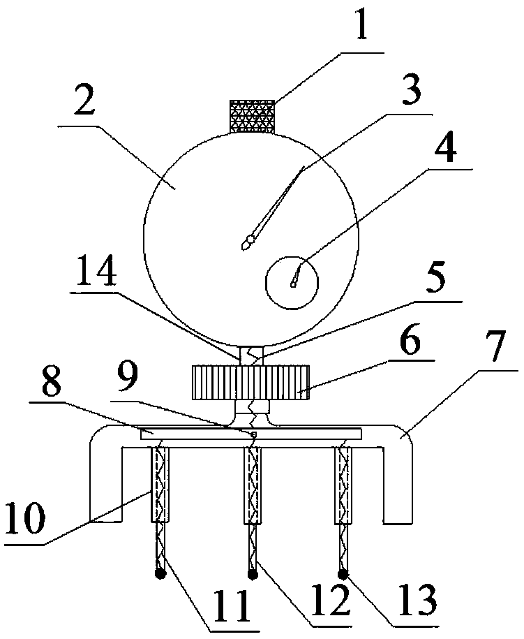
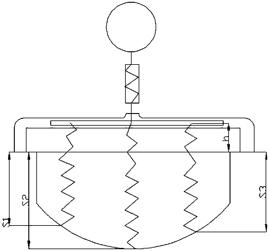
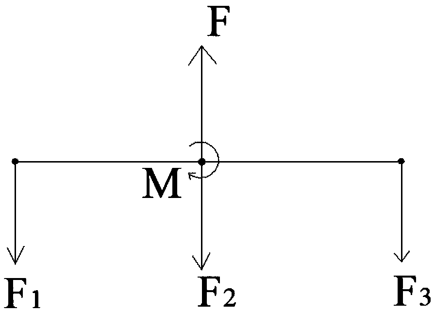
[0015] Such as figure 1 As shown, a measuring device for the average corrosion depth in an X-ray stress test includes a support 7, a support rod 14, and a dial gauge 2. The support is a "U"-shaped hollow bending piece with an opening facing down, which can be A support is formed on the horizontal surface around the corrosion pit of the test object. The support rod is a hollow straight rod. The upper and lower ends of the support rod are respectively connected to the center of the top of the support and the center of the bottom of the dial indicator. A balance plate 8 is horizontally arranged in the cavity on the top of the support. , The center of the balance board is connected to the support through the pin 9; the balance board is provided with a rotating spring, and the bottom surface of the support is ev...


PUM


Abstract

The invention provides a measurement device for average corrosion depth in X-ray stress testing.The measurement device comprises a support, a supporting rod and a dial gauge.The support is a U-type hollow bent part with a downward opening, the supporting rod is a hollow straight rod, the upper end and the lower end of the supporting rod are connected with the center of the top of the support and the center of the bottom of the dial gauge, a balance plate is horizontally arranged inside a cavity in the top of the support, the center of the balance plate is connected with the support through a pin shaft, a rotating spring is arranged on the balance plate, three sleeves are evenly arranged on the bottom surface of the support at intervals, the center of the top face of the balance plate is connected with the bottom end of a main spring, the top end of the main spring is connected with the dial gauge, the bottom face of the balance plate is spaced evenly and connected with the top ends of three auxiliary springs, spheres are arranged at the bottom ends of the auxiliary springs which are sleeved with sheaths, the bottom ends of the sheaths are fixedly connected with the spheres, the three auxiliary springs and the three sleeves are arranged correspondingly, and the sheaths are inserted into the sleeves and can slide along the sleeves.On the premise of guaranteeing testing precision, the average depth of a corrosion pit is tested in a one-off mode, and working efficiency and accuracy are substantially improved.

Description

Technical field [0001] The invention belongs to the technical field of residual stress testing, and in particular relates to a measuring device for average corrosion depth in X-ray stress testing. Background technique [0002] In industrial production, the problem of residual stress is very prominent. Under the combined action of working temperature, working medium and residual stress, on the one hand, the product or workpiece will reduce the strength, causing the workpiece to produce deformation and cracking and other process defects; on the other hand, it will cause the natural release process after manufacturing. The size of the workpiece changes or its fatigue strength, stress corrosion and other mechanical properties are reduced. Therefore, the research of residual stress measurement technology is of great significance for ensuring product quality or the safety and reliability of workpieces. The X-ray diffraction method is based on the theory of elasticity and X-ray crysta...

Claims


Application Information

Patent Timeline
Patent Type & Authority Patents(China)
IPC IPC(8): G01B5/18
CPCG01B5/18
Inventor 薛欢葛锐马玉喜凃应宏张彤严龙邝兰翔朱琳娜
Owner 武汉钢铁有限公司
Learn More