Heat pump-type vermicelli drying equipment

A technology of drying equipment and heat pump, applied in lighting and heating equipment, drying gas arrangement, progressive dryer, etc., which can solve the problems of low energy efficiency, waste of heat, weakening of energy saving advantages, etc.

Inactive Publication Date: 2016-07-20
HENAN BAIHENG ENERGY SAVING TECH
View PDF4 Cites 6 Cited by
  • Summary
  • Abstract
  • Description
  • Claims
  • Application Information

AI Technical Summary

Problems solved by technology

At present, the heat pump drying equipment is limited by the characteristics of the heat pump. In the lower ambient temperature, the heating capacity and energy efficiency ratio of the heat pump are relatively low. Because the drying process of the material is not affected by the season and the ambient temperature, the drying process will be carried out throughout the year, so in the selection Heat pumps are often matched according to the heat load at low ambient temperature. At this time, the selection of heat pump equipment will be large, which not only increases the initial investment of drying equipment, but also lowers the energy efficiency of heat pump drying equipment at low ambient temperature. Energy-saving advantages Weakened, and when the ambient temperature is high, the utilization rate of the heat pump equipment is very low
On the other hand, the hot and humid air discharged from the heat pump drying equipment is not effectively utilized, and most of the heat is discharged into the environment, resulting in waste of heat

Method used


Image

  • Heat pump-type vermicelli drying equipment
  • Heat pump-type vermicelli drying equipment
  • Heat pump-type vermicelli drying equipment

Examples


Embodiment Construction

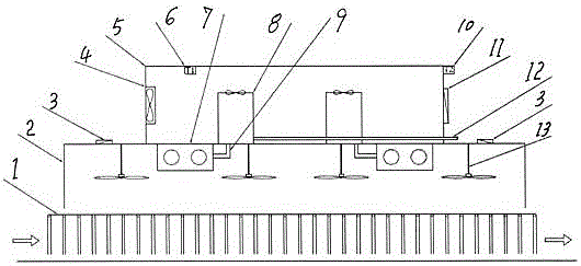
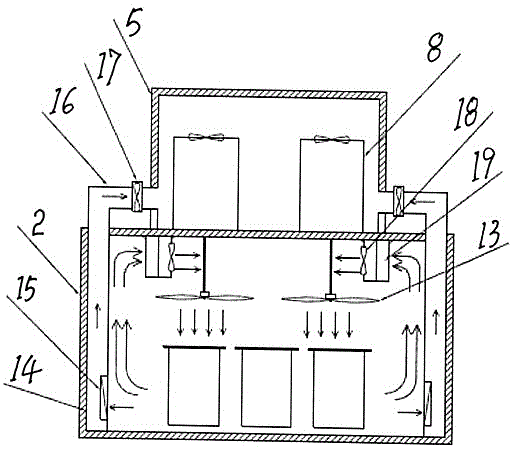
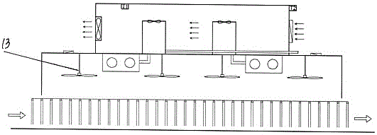
[0009] Embodiments are described in detail in conjunction with the above accompanying drawings, as figure 1 with figure 2 As shown, the drying equipment is mainly composed of a drying chamber 2, a noodle conveying line 1, a hot air blower 7, a dehumidification system 14, a heat pump host 8, a heat pump host room 5, a fresh air damper 3 and a drainage system 12. 2 is located in the lower part of the heat pump host room 5, one end of the drying room is provided with the entrance of the noodle conveying line 1, and the other end is the outlet, and the hot air blower 7 is suspended on the top of the drying room, and the hot air blower 7 includes the condenser of the heat pump 19 and circulation fan 18, the ceiling fan 13 is suspended on the top of the drying room, the dehumidification system 14 is located at the bottom of the drying room, and the dehumidification system is placed at the bottom of the drying room by one end of the dehumidification air pipe, and the other end is co...


PUM


Abstract

The invention discloses heat pump-type vermicelli drying equipment. The heat pump-type vermicelli drying equipment comprises a drying chamber, wherein the drying chamber is located on the lower part of a heat pump machine chamber; one end of the drying chamber is provided with the inlet of a vermicelli conveying line; the other end of the drying chamber is an outlet; hot-air blowers are hung on the top of the drying chamber; each hot-air blower comprises a condenser for a heat pump and a circulation fan; hanging fans are hung on the top of the drying chamber; a dehumidification system is located on the bottom of the drying chamber; the dehumidification system is characterized in that one end of each dehumidification air pipe is arranged at the bottom of the drying chamber, and the other end of each dehumidification air pipe is connected to the inlet of the heat pump machine chamber; the inlets of the heat pump machine chamber are provided with dehumidification fans; outlets in the bottoms of the dehumidification air pipes are provided with dehumidification air doors; the heat pump machine chamber is located on the upper part of the drying chamber; at least one heat pump main machine is arranged in the heat pump machine chamber; the front side wall of the heat pump machine chamber is provided with an air exhaust fan; an air exhaust air door is arranged on the rear side wall of the heat pump machine chamber; fresh air doors are arranged on the upper part of the drying chamber; and one end of each heat pump main machine is connected with a water drainage system.

Description

Technical field: [0001] The invention relates to the field of heat pump drying equipment, in particular to the technical field of food processing equipment, and is especially suitable for drying vermicelli. Background technique: [0002] At present, air source heat pumps are mostly used for dry noodles. The heated air is sent into the drying room, and it is directly discharged in the form of waste gas after heat exchange with the noodles. However, the waste gas contains steam latent heat and high-temperature sensible heat, resulting in a lot of waste of energy. Moreover, the air source heat pump is greatly affected by the ambient temperature, which is not conducive to large-scale application across the country. [0003] As we all know, heat pump drying equipment is a special equipment for drying materials. The heat pump provides heat supply for the drying equipment, and sends the heated airflow into the drying chamber. The high-temperature dry airflow takes away the water va...

Claims


Application Information

Patent Timeline
Patent Type & Authority Applications(China)
IPC IPC(8): F26B15/12F26B21/00F26B21/04F26B21/10A21C14/00
CPCY02P60/80F26B15/126A21C14/00F26B21/001F26B21/04F26B21/10F26B2210/06
Inventor 程烨朱景申冯云鹏李兴书闫小广李童庞俊峰李霖
Owner HENAN BAIHENG ENERGY SAVING TECH
Why Eureka
Try Eureka