Bearing end cover and bearing seat provided with same

A technology of bearing end cover and bearing, which is applied to the rigid support of bearing components, bearing elements, shafts and bearings, etc., which can solve the problems of inconvenient installation of bearings, increased air pressure, and increased damage rate of bearings and bearing end covers.

Inactive Publication Date: 2016-07-20
ZHUHAI GREE REFRIGERATION TECH CENT OF ENERGY SAVING & ENVIRONMENTAL PROTECTION
View PDF5 Cites 1 Cited by
  • Summary
  • Abstract
  • Description
  • Claims
  • Application Information

AI Technical Summary

Problems solved by technology

[0002] The bearing end cover has a blind hole for bearing installation. When the bearing is pressed into the blind hole for bearing installation, the air in the blind hole for bearing installation will be compressed rapidly, resulting in a sudden increase in air pressure, which is not only inconvenient to install the bearing, but also causes The damage rate of the end cap is greatly increased
At present, in order to solve the above-mentioned technical problems, such as the utility model patent application titled "a bearing end cover" with the application number 201320418439.7, an exhaust groove is provided on the hole wall of the bearing installation blind hole, and when the bearing is pressed into the bearing installation blind When the hole is installed, the gas in the blind hole of the bearing installation is discharged through the exhaust groove, which avoids the sudden increase of the air pressure in the blind hole of the bearing installation, and thus avoids the damage of the bearing cover. Axially parallel, that is to say, a certain extension line parallel to the axis of the bearing installation blind hole on the wall of the bearing installation blind hole will pass through the exhaust groove. With the above structure, the bearing outer ring and the bearing installation The contact part of the blind hole wall has an exhaust groove, and the bearing installation blind hole wall will appear in the entire axial position (that is, an extension line above) in an area that cannot provide support for the bearing (that is, the exhaust groove) , which leads to unbalanced force on the rotor of the motor used to drive the inner ring of the bearing and brings periodic impact to the rotation of the motor. The motor runs unstable and reduces the service life of the motor.

Method used


Image

  • Bearing end cover and bearing seat provided with same
  • Bearing end cover and bearing seat provided with same

Examples


Embodiment Construction

[0020] It should be noted that, in the case of no conflict, the embodiments in the present application and the features in the embodiments can be combined with each other. The present invention will be described in detail below with reference to the accompanying drawings and examples.

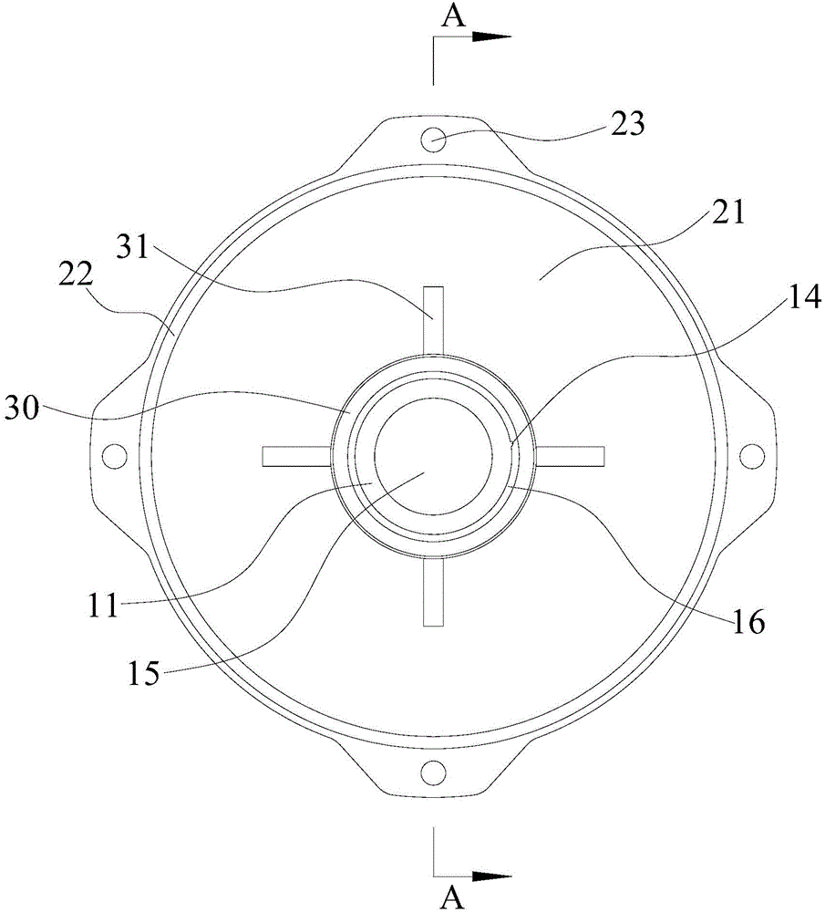
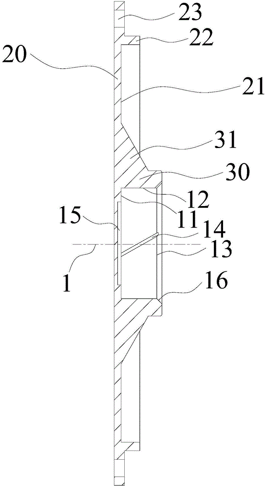
[0021] Such as figure 1 and figure 2 As shown, the bearing end cover of this embodiment includes a blind hole for bearing installation. The blind hole for bearing installation has a hole bottom 11 and a hole wall 12. The hole wall 12 forms a bearing entry end 13. The hole wall 12 is provided with an exhaust groove 14. The air groove 14 extends in the direction from the hole bottom 11 to the bearing inlet end 13. It is characterized in that the exhaust groove 14 has a deviation section that deviates from the extension line 1, that is, the deviation section does not coincide with the extension line 1, wherein, The extension line 1 is any extension line on the hole wall 12 parallel to the axis ...


PUM


Abstract

The invention provides a bearing end cover and a bearing seat provided with the same. The bearing end cover comprises a bearing installation blind hole provided with a hole bottom (11) and a hole wall (12), wherein the hole wall (12) forms a bearing inlet end (13); an exhaust groove (14) is arranged in the hole wall (12); the exhaust groove (14) extends in a direction from the hole bottom (11) to the bearing inlet end (13); and the exhaust groove (14) is provided with a deflection section deflecting from an extension line (1), wherein the extension line (1) is any extension line parallel to the axis of the bearing installation blind hole, on the hole wall (12). According to the technical scheme of the invention, shortening of the service life of a motor used for driving a bearing to rotate can be avoided on the basis of facilitating installation of the bearing.

Description

technical field [0001] The invention relates to the technical field of bearing installation, in particular, to a bearing end cover and a bearing seat with the same. Background technique [0002] The bearing end cover has a blind hole for bearing installation. When the bearing is pressed into the blind hole for bearing installation, the air in the blind hole for bearing installation will be compressed rapidly, resulting in a sudden increase in air pressure, which is not only inconvenient to install the bearing, but also causes The damage rate of the end cap is greatly increased. At present, in order to solve the above-mentioned technical problems, such as the utility model patent application titled "a bearing end cover" with the application number 201320418439.7, an exhaust groove is provided on the hole wall of the bearing installation blind hole, and when the bearing is pressed into the bearing installation blind When the hole is installed, the gas in the blind hole of the...

Claims


Application Information

Patent Timeline
IPC IPC(8): F16C35/00
Inventor 黄男吴雨顺周成海刘丽刚陈鹤碧
Owner ZHUHAI GREE REFRIGERATION TECH CENT OF ENERGY SAVING & ENVIRONMENTAL PROTECTION
Why Eureka
Try Eureka