
Semi-continuous microwave catalytic thermal cracking reactor

A microwave catalysis, semi-continuous technology, applied in the detailed information of chemical/physical/physical chemical reactors, chemical instruments and methods, chemical/physical processes, etc., to achieve full reaction, solve the problem of material accumulation, and increase the distance of material movement Effect

Inactive Publication Date: 2016-07-20
JIANGSU UNIV
View PDF11 Cites 8 Cited by
  • Summary
  • Abstract
  • Description
  • Claims
  • Application Information

AI Technical Summary

Problems solved by technology

[0003] The purpose of the present invention is to provide a kind of semi-continuous microwave catalytic pyrolysis reactor, to improve the problem of its material accumulation, stability when heating and improve conversion rate, and catalyzing fixed bed unit is integrated wherein, to improve the obtained Product selectivity, lower production costs

Method used


Image

  • Semi-continuous microwave catalytic thermal cracking reactor
  • Semi-continuous microwave catalytic thermal cracking reactor
  • Semi-continuous microwave catalytic thermal cracking reactor

Examples


Embodiment 1

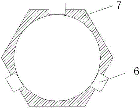
[0022] Such as figure 1 The shown semi-continuous microwave catalytic thermal cracking reactor includes a heating chamber 7 and a microwave heating source 6; wherein the heating chamber 7 is provided with a gas inlet 5, a gas outlet 1, a feed port 2, a feed port 8 and Two temperature measuring ports 4; the feed port 2 is equipped with a feed regulating device 3 to control the feed speed. The microwave heating source 6 outside the heating chamber is adjusted by the control panel 9. The axis of the heating chamber 7 extends in the vertical direction, and a plurality of groups of microwave heating sources 6 are arranged outside of the heating chamber 7, and each group is composed of three microwave heating sources, and they are on the same vertical axis.

[0023] Such as figure 2 The schematic diagram of the top view of the heating chamber shown, the heating chamber 7 has a regular hexagonal structure; the gas inlet 5 is used to pass nitrogen in the experiment to ensure that the e...

Embodiment 2

[0028] Such as Figure 5 As shown, an umbrella-shaped partition is placed in the heating chamber, and the partition is composed of two umbrella-shaped structures. After the material enters the heating chamber through the inlet, it slides down through the outer surface of the umbrella structure. The diameter of the first umbrella structure is 3 to 4 cm smaller than the diameter of the heating chamber; the material falls into the second through the first umbrella edge Inside an inverted umbrella-shaped structure, the diameter of the umbrella-shaped structure is only slightly smaller than the diameter of the heating chamber; the material passes through the umbrella-shaped place a, and drops downward into the second group of umbrella-shaped structures.

[0029] Image 6 It is an enlarged view at a. In this figure, a1 is a pole, which supports the inverted umbrella structure, and a2 is the main pole, which supports the entire structure. The bottom of the inverted umbrella-shaped struc...


PUM


Abstract

The invention discloses a semi-continuous microwave catalytic thermal cracking reactor. The semi-continuous microwave catalytic thermal cracking reactor of a vertical structure comprises a heating chamber, a microwave heating source and a catalytic static bed device. The cross section of the heating chamber is orthohexagonal. An inner quartz reaction cavity is formed in the heating chamber. Materials react in the inner quartz reaction cavity. Two groups of umbrella-shaped partition boards are arranged in the inner quartz reaction cavity. The upper umbrella-shaped structure is smaller than the lower umbrella-shaped structure in each group so as to enable the materials to slide down from top to bottom, and accordingly, motion paths of the materials are increased. The umbrella-shaped partition boards can be rotated according to needs. Three groups of microwave heating sources extending to the heating chamber are provided. The axes of each group of microwave heating sources do not coincide so as to reduce mutual interference. The catalytic static bed device can be mounted in the reactor, the reactor is provided with two temperature measurement openings, and one of the temperature measurement openings is used according to needs. The semi-continuous microwave catalytic thermal cracking reactor has the advantages that biomass conversion rate can be increased, heating stability can be improved and heating and catalyzing are integrated, and can be applied to the fields such as energy and chemical industry.

Description

technical field [0001] The invention belongs to the technical field of microwave reactors, and relates to a microwave catalytic pyrolysis technology, which improves the conversion rate and product selectivity of biomass reactions. technical background [0002] With the utilization and development of biomass, microwave pyrolysis technology has developed into a new type of pyrolysis technology in recent years. The microwave heating rate is fast, the energy consumption is small, and it is easy to control. The particles in the material vibrate under the action of microwaves, which causes violent friction between the material particles and converts electromagnetic energy into heat energy. Microwave thermal cracking technology is to heat the raw material to 300-650°C by microwave under the condition of no oxygen, crack it into low-molecular organic vapor in a short time, and obtain liquid product after rapid cooling. Compared with the traditional pyrolysis method, the microwave p...

Claims


Application Information

Patent Timeline
Patent Type & Authority Applications(China)
IPC IPC(8): B01J8/02B01J19/12B01J19/00
CPCB01J8/02B01J19/006B01J19/126B01J2219/00763B01J2219/1206
Inventor 卜权梁江辉向忠平施爱平
Owner JIANGSU UNIV
Learn More