An air compressor split type three-stage oil-gas separation device

A separation device and split-type technology, which is applied in the direction of combined devices, separation methods, and dispersed particle separation, can solve the problems of low oil-gas separation efficiency, difficulty in manufacturing cyclone separation cylinders and filter element separation cylinders, and impossibility of using filter element separation cylinders. Cyclone method and other problems, to achieve the effect of improving filtration accuracy and operation stability, fine oil-gas separation effect, and outstanding oil-gas separation performance

Inactive Publication Date: 2018-08-21
釜玛机械(江苏)有限公司
View PDF13 Cites 0 Cited by
  • Summary
  • Abstract
  • Description
  • Claims
  • Application Information

AI Technical Summary

Problems solved by technology

[0005] (1) The oil-gas separator still adopts an integrated structure, and the manufacturing of the cyclone separation cylinder and the filter element separation cylinder is difficult, and the structural design has great limitations, and it is not conducive to the shape and layout of the air compressor, so it is difficult to really popularize and use;
[0006] (2) Due to the integrated structure design, the filter element separation cylinder cannot use the cyclone method to enter the air, and can only achieve two-stage oil-gas separation, and the oil-gas separation efficiency is low;
[0007] (3) Due to the integrated structure design, the layout of the mixed gas inlet and the oil return port is limited, and both the cyclone separation cylinder and the filter element type separation cylinder adopt upper air intake, which increases the load on the filter element; and, the cyclone separation cylinder and the filter element type separation The oil return port of the barrel is directly connected to the lubrication system of the air compressor, which is not conducive to the rapid discharge of residual oil during the test run, thereby affecting the separation performance of the oil separation core, which is also a common defect of the existing air compressor oil-gas separator; and the oil return The outlet is set at the lowest position, and the sewage outlet cannot be effectively installed, resulting in more impurities in the lubricating oil, which affects the service life of the air compressor

Method used


Image

  • An air compressor split type three-stage oil-gas separation device
  • An air compressor split type three-stage oil-gas separation device
  • An air compressor split type three-stage oil-gas separation device

Examples


Embodiment

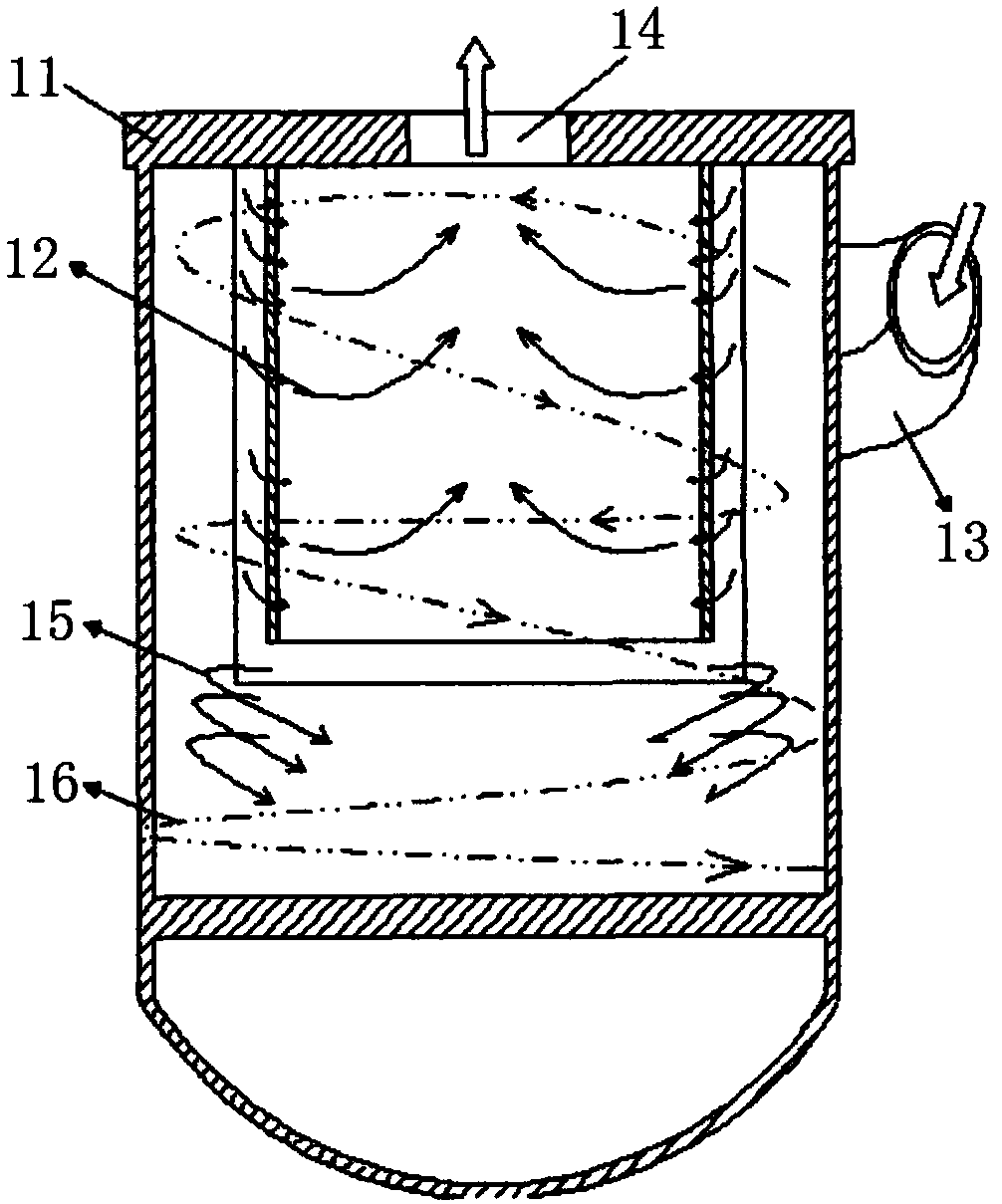
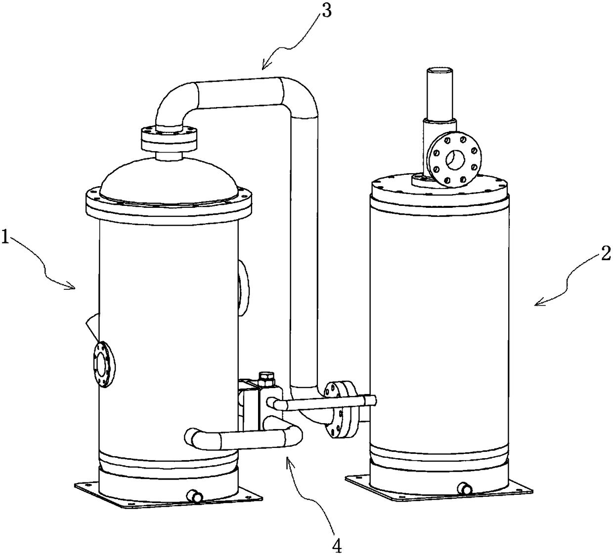
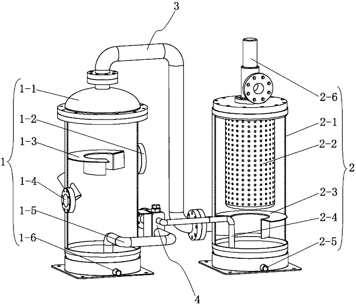
[0038] Combine figure 2 As shown, an air compressor split three-stage oil and gas separation device of this embodiment includes a first oil and gas barrel 1 and a second oil and gas barrel 2 separately arranged, a gas outlet of the first oil and gas barrel 1 and a second oil and gas barrel 2 The gas inlets are connected by the oil and gas pipeline 3. The first oil and gas barrel 1 is used for primary oil and gas separation, and its main function is to store oil, and the second oil and gas barrel 2 is used for secondary and tertiary oil and gas separation, and its main function is fine It separates oil and gas and can also be used as a buffer gas tank. In this embodiment, the oil and gas separation device is cleverly designed into two parts, the first oil and gas barrel 1 and the second oil and gas barrel 2, which are separately arranged. The volume of the first oil and gas barrel 1 and the second oil and gas barrel 2 is lighter, easier to manufacture, and more layout. Flexible...


PUM


Abstract

The invention discloses an air compressor split type three-stage oil-gas separation device, which belongs to the technical field of oil-gas separation. The invention comprises first and second oil and gas barrels which are arranged separately, and the gas outlet of the first oil and gas barrel is connected with the gas inlet of the second oil and gas barrel through an oil and gas pipeline; the first oil and gas barrel includes a first cylinder body, a first inlet The air port, the first air inlet guard plate and the first oil return pipe; the second oil and gas barrel includes the second cylinder body, the oil separation core, the second air inlet guard plate and the second oil return pipe; it also includes the first oil return pipe and the second oil return pipe respectively The two oil return pipes are connected and have a mixed flow assembly for regulating the flow of the second oil return pipe. The invention uses the first oil-gas barrel and the second oil-gas barrel to realize the three-stage separation of the mixed gas, the first oil-gas barrel is used as the oil storage part, the second oil-gas barrel is used as the oil separation core separation part, and also serves as a buffer gas tank, which can further improve the air The filtration accuracy and operation stability of the compressor; at the same time, the volume is lighter, the layout of the air compressor is easier, and the installation and maintenance are more convenient.

Description

Technical field [0001] The invention relates to an oil and gas separator, and more specifically, to a split three-stage oil and gas separation device for an air compressor. Background technique [0002] The air compressor is mainly composed of a main engine, a motor, an oil and gas separation system, a cooling system, a control system, and a main frame. The air passes through the intake filter to remove dust or impurities in the atmosphere, and then enters the main compressor through the intake control valve , During the compression process, it is mixed with the injected cooling lubricating oil, and the compressed mixed gas is discharged from the compression chamber into the oil-gas separator. At this time, the compressed oily gas discharges through collision, interception, and gravity, and most of the oil The medium is separated, and then enters the oil and gas fine separator for secondary separation, so that the oil content of the compressed air is further reduced. When the air...

Claims


Application Information

Patent Timeline
Patent Type & Authority Patents(China)
IPC IPC(8): B01D50/00
CPCB01D50/20
Inventor 金度亨丁习锋许孟龙
Owner 釜玛机械(江苏)有限公司
Why Eureka
Try Eureka