Dedusting device for cement plants

A dust removal device and a technology for a cement plant, applied in the field of cement manufacturing, can solve the problems of not being able to exhaust and dredging pipes by themselves, endangering the health of workers on the post, and aggravating pipe blockages, etc.

Inactive Publication Date: 2016-07-20
CHONGQING JINBO IND GRP
View PDF0 Cites 0 Cited by
  • Summary
  • Abstract
  • Description
  • Claims
  • Application Information

AI Technical Summary

Problems solved by technology

[0002] The production of cement is the process of manufacturing powdery substances. A large amount of dust is generated in the production process. If the dust pollution is not controlled, it will not only endanger the health of the workers and pollute the environment, but also increase the mechanical wear and electrical failure of the equipment.
[0003] The existing dust removal devices in cement plants often use bag dust collectors. The dust removal effect is poor, the wind force is small, and the internal pipes are often blocked. The elbow needs to be cleaned at least once a year by lowering the flange.
Due to the large resistance of the filter bag and blockage, the ventilation rate of the bag filter has dropped significantly (the measured average value is 561m3 / h), which is much lower than the nameplate value (900m3 / h)
[0004] The existing dust removal device in the cement plant only has the function of suction, and cannot exhaust itself to clear the pipeline itself, which further aggravates the blockage of the pipeline

Method used


Image

  • Dedusting device for cement plants
  • Dedusting device for cement plants
  • Dedusting device for cement plants

Examples


Embodiment Construction

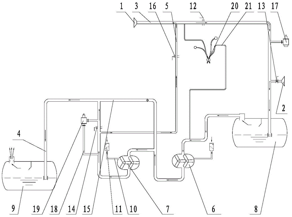
[0028] see figure 1 , is a preferred embodiment of a dust removal device used in a cement plant, including a first air inlet hopper 1, a second air inlet hopper 2, an air extraction pipe 3, an exhaust pipe 4, and an air supply pipe 5 for providing dust removal Power primary vacuum pump 6, secondary vacuum pump 7, first filter 8 and second filter 9 for filtering cement ash. Preferably, the casings of the primary and secondary vacuum pumps 7 are manufactured in one piece, with a high degree of integration, smaller space occupation, and convenient installation and transportation. Further preferably, the casings of the primary and secondary vacuum pumps 7 are respectively provided with cooling air ducts 10, one end of the cooling air ducts 10 communicates with the pump cavity of the corresponding vacuum pump, and the other end is connected to the air filter 11, and the cooling air The pipe 10 is provided with a cooling air one-way valve, so that the cooling air enters the pump ch...


PUM


Abstract

The invention discloses a dedusting device for cement plants. The dedusting device can radically remove dusts, and the obstruction of pipeline is avoided. The dedusting device comprises a first air intake bucket, a second air intake bucket, an air suction pipe, a gas discharge pipe, an air supply pipe, a primary vacuum pump, a secondary vacuum pump, a first filter, and a second filter. One end of the air suction pipe is connected to the first air intake bucket, the other end is connected to the first filter; the air suction pipe is provided with a first air inlet control valve; the air outlet end of the first filter is connected to the primary vacuum pump and the secondary vacuum pump, the cavity of the first vacuum pump is larger than the cavity of the secondary vacuum pump; the air outlet end of the secondary vacuum pump is connected to the second filter through the gas discharge pipe, a second control valve is arranged on the gas discharge pipe; a unidirectional pipe is arranged between the second control valve and the second filter; one end of the unidirectional pipe is connected to a position between the primary vacuum pump and the second vacuum pump so as to form a passage between the primary vacuum pump and the second filter; one end of the air supply pipe is connected to the air outlet end of the secondary vacuum pump, the other end is connected to a position between the first control valve and the first air intake bucket, and a third control valve is arranged on the air supply pipe.

Description

technical field [0001] The invention relates to the field of cement production, in particular to a dust removal device used in cement plants. Background technique [0002] The production of cement is the process of manufacturing powdery substances. A large amount of dust is generated in the production process. If the dust pollution is not controlled, it will not only endanger the health of workers and pollute the environment, but also increase the mechanical wear and electrical failure of equipment. [0003] The existing dust removal devices in cement plants often use bag dust collectors. The dust removal effect is poor, the wind force is small, and the internal pipes are often blocked. The elbow needs to be cleaned at least once a year by lowering the flange. Due to the large resistance of the filter bag and blockage, the ventilation rate of the bag filter has dropped significantly (the measured average value is 561m3 / h), which is much lower than the nameplate value (900m3 / ...

Claims


Application Information

Patent Timeline
IPC IPC(8): B01D47/02
Inventor 刘定华杨中平赵光林彭代春
Owner CHONGQING JINBO IND GRP
Why Eureka
Try Eureka