A flexible base for preventing back-absorption after ejection

A technology of flexible base and bottom plate, applied in the direction of launching device, etc., can solve the problems of endangering the use safety of internal equipment, sucking back large deformation impact load, etc., and achieve the effect of simple structure, improved safety and convenient use.

Active Publication Date: 2019-08-30
BEIJING INST OF SPACE LAUNCH TECH +1
View PDF4 Cites 0 Cited by
  • Summary
  • Abstract
  • Description
  • Claims
  • Application Information

AI Technical Summary

Problems solved by technology

However, in practical applications, due to the aftereffect of ejection, the pressure inside the launch tube will be lower than the pressure outside the tube and will attenuate according to the sine wave
However, under the action of the pressure difference inside and outside the launch tube, the flexible base will produce a large deformation in the direction of the launch tube and generate an impact load. Once it contacts the equipment inside the launch tube, it will cause damage, thus endangering the internal equipment. safe to use

Method used


Image

  • A flexible base for preventing back-absorption after ejection
  • A flexible base for preventing back-absorption after ejection
  • A flexible base for preventing back-absorption after ejection

Examples


Embodiment Construction

[0017] First of all, it needs to be explained that the orientation words such as front, back, left, right, up, and down in the present invention are only described according to the accompanying drawings, so as to facilitate understanding, and are not intended to limit the technical solutions and scope of protection of the present invention. .

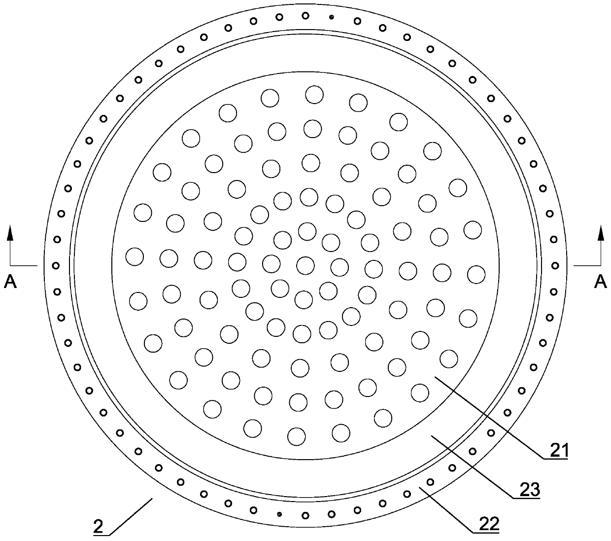
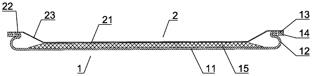
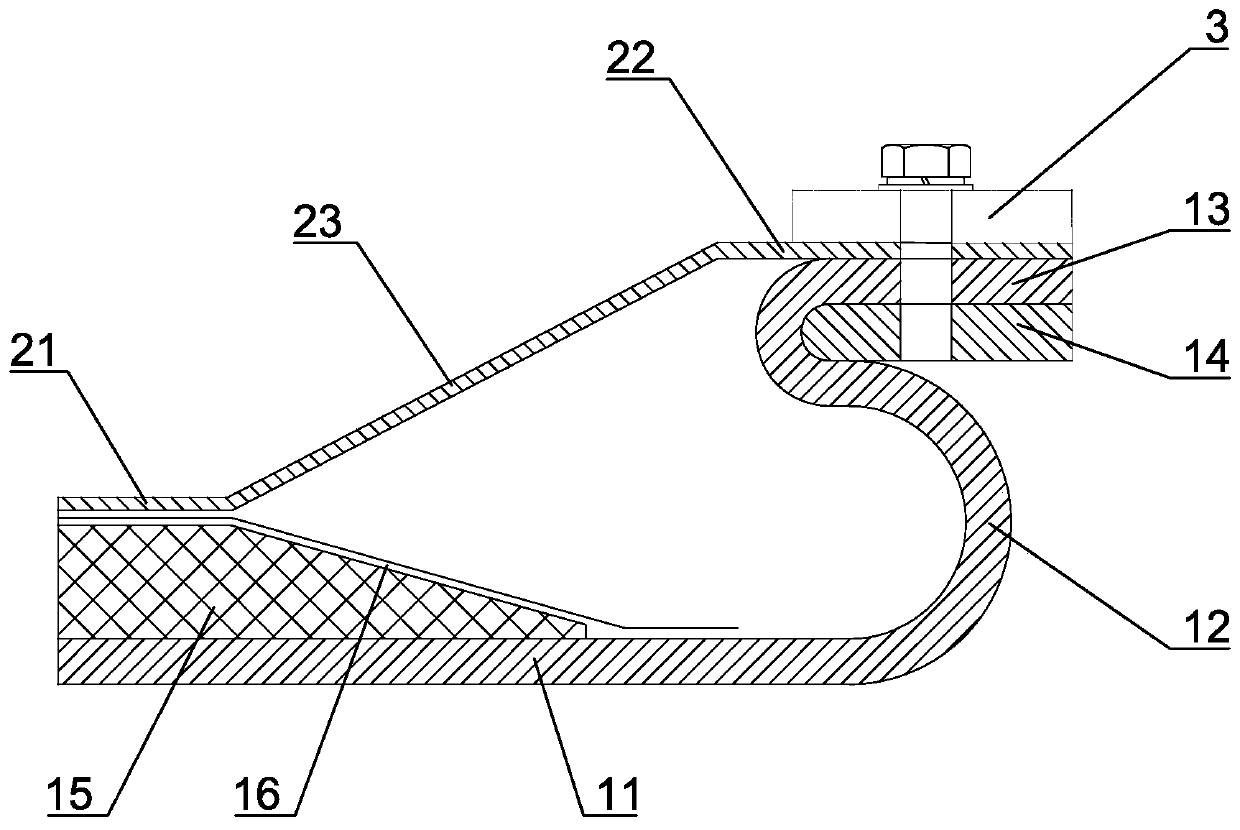
[0018] Such as Figure 1 to Figure 3 Shown is a specific embodiment of a flexible base for preventing suckback after ejection of the present invention, including a base body 1 and a protective screen 2 . The base body 1 specifically includes a bottom plate 11 and a peripheral wall 12 connected to the periphery of the bottom plate 11 , a first flange 13 is provided on the upper end of the peripheral wall 12 , and a second metal flange 14 is provided on the lower side of the first flange 13 . The first flange 13 is provided with a plurality of evenly distributed first installation holes along the circumference, and the second flange 14 i...


PUM


Abstract

The invention relates to a flexible base preventing back sucking during a catapulting aftereffect stage. The flexible base preventing back sucking during the catapulting aftereffect stage comprises a base body and a protective net plate; the base body comprises a bottom plate and peripheral walls fixedly connected with the periphery of the bottom plate; a first flange is arranged at the upper end of the peripheral wall; a second flange of a metal material is arranged on the lower side of the first flange; a plurality of evenly distributed first installing holes are formed in the first flange in the peripheral direction; the second flange is provided with a plurality of second installing holes corresponding to the first installing holes in the first flange in the peripheral direction; the protective net plate is provided with a plurality of ventilating holes; and the protective net plate is arranged on the upper side of the base body and is made to be provided with a plurality of third installing holes corresponding to the first installing holes in the first flange in the peripheral direction. The flexible base preventing back sucking during the catapulting aftereffect stage has the beneficial effects of being simple in structure, convenient to use, safe and reliable, and effectively solves the problem that impacting loads generated because of back sucking of the flexible base during the catapulting aftereffect stage endanger equipment in a launch canister.

Description

technical field [0001] The invention relates to a missile launching device, in particular to a flexible base for transmitting ejection loads. Background technique [0002] In the military field, as the key equipment of the cold launch device, the missile launching tube usually needs to be provided with a flexible base at the rear to transfer the recoil (ejection) load generated by the ejection gas pressure in the launching tube to the ground and reduce the impact on the launching vehicle . In order to adapt to the uneven working conditions of the ground, the flexible base needs to leave a certain gap with the ground after installation. Under the action of the air pressure generated by the missile launch, the flexible base will contact the ground through its own flexible deformation to realize the ejection load transfer. However, in practical applications, due to the aftereffect of ejection, the pressure inside the launch tube will be lower than the pressure outside the tub...

Claims


Application Information

Patent Timeline
Patent Type & Authority Patents(China)
IPC IPC(8): F41F1/00
Inventor 邢春鹏吴新跃赵衡柱刘宝龙刘懿敏
Owner BEIJING INST OF SPACE LAUNCH TECH
Why Eureka
Try Eureka