
Special-shaped side branch balloon stent system for bifurcation lesion interventional therapy

A stent system and side branch technology, applied in the field of medical devices, can solve side branch restenosis, increase restenosis, side branch guide wire enters through the main branch stent mesh or main branch guide wire passes through the side branch stent mesh To achieve the effect of avoiding plaque displacement, reducing restenosis, and reducing the possibility of acute thrombosis

Inactive Publication Date: 2016-07-20
张健
View PDF18 Cites 0 Cited by
  • Summary
  • Abstract
  • Description
  • Claims
  • Application Information

AI Technical Summary

Problems solved by technology

In addition to the relatively complicated operation, for example, the guide wire is not easy to pass through the mesh of the main branch stent and enter the side branch vessels, and the balloon may rupture when it passes through or expands the mesh, etc. Others include: 1. Possible damage when the guide wire is withdrawn The opening of the side branch or the displacement of the stent; Second, the entry of the side branch guide wire through the mesh of the main branch stent or the passage of the main branch guide wire through the mesh of the side branch stent cannot ensure that the guide wire is well positioned on the central axis of the vascular lumen. During the balloon expansion process, the force on the vessel wall will be affected by uncertainty; 3. There is an unnecessary layer or two layers of metal mesh at the opening of the side branch, and some main stents may have three layers of metal mesh at both ends, increasing Fourth, if there are many side branch stents protruding from the main branch, the balloon is longer in the main branch. When the main branch balloon expands, the side branch stent migrates into the side branch, which increases the damage to the tube wall and is easy tearing of the inner membrane
5. There are too many parallel parts of the two balloons during kissing expansion, which may cause the gap at the acute angle of the opening to become longer and the obtuse angle to be over-expanded; 6. Traditional balloon expansion and stent release do not achieve the opening of the side branch The good fit of the arc-shaped transition zone in physical form is also one of the reasons for the easy formation of side branch restenosis and thrombosis after operation; shape uncertainty etc.
The main reasons for these problems may be that the operator is limited to the current instrumentation, the lack of a stent and balloon tailored to the physical shape of the bifurcation vessel opening, and the lack of a suitable balloon stent delivery system

Method used


Image

  • Special-shaped side branch balloon stent system for bifurcation lesion interventional therapy
  • Special-shaped side branch balloon stent system for bifurcation lesion interventional therapy
  • Special-shaped side branch balloon stent system for bifurcation lesion interventional therapy

Examples


Embodiment 1

[0078] Example 1: Special side support balloon stent system without stent

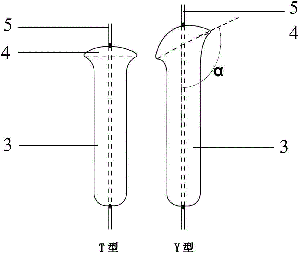
[0079] A special type side branch balloon stent system for bifurcation lesions. The special type side branch balloon stent system includes: a side branch balloon body 3, which is expanded to fit the flared side support ball at the opening of the side branch The head end of the balloon type end 4 and the side branch balloon catheter 5 penetrates the side branch balloon body 3.

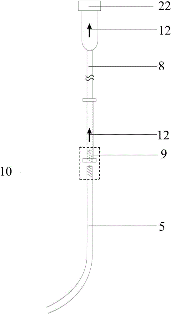
[0080] The side branch balloon catheter 5 has a side branch balloon guide wire cavity 6 and a side branch balloon compression cavity 7 inside.

[0081] The cross section where the side branch balloon characteristic end 4 and the side branch balloon body 3 are connected is at a certain angle with the central axis of the side branch balloon body 3; among them: the T-shaped stent balloon system for T-shaped lesions, clamps The angle is 90 degrees; for the Y-type stent balloon system for Y-type lesions, the included angle α toward the hea...

Embodiment 2

[0085] Example 2: Special side support balloon stent system with stent

[0086] A special type side branch balloon stent system for bifurcation lesions. The special type side branch balloon stent system includes: a side branch balloon body 3, which is expanded to fit the flared side support ball at the opening of the side branch The head end of the balloon type end 4 and the side branch balloon catheter 5 penetrates the side branch balloon body 3.

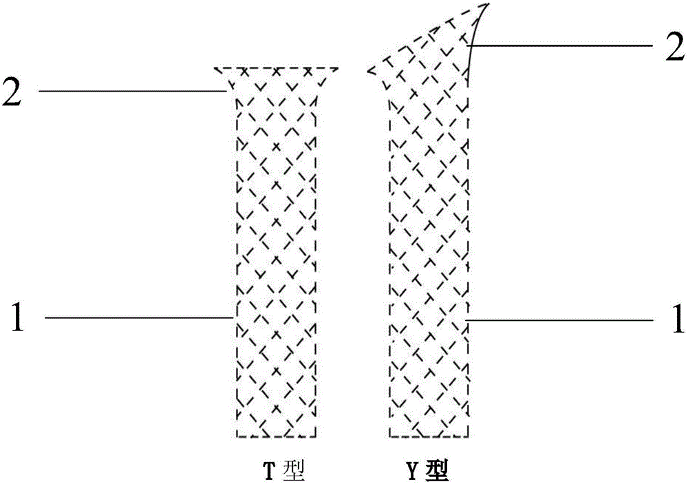
[0087] The special-shaped side support balloon stent system further includes a side support stent body 1, a bell-shaped side support stent special end 2 at the side branch opening after expansion, and the side support stent body 1 is sleeved on the side support balloon body 3. .

[0088] The side branch balloon catheter 5 has a side branch balloon guide wire cavity 6 and a side branch balloon compression cavity 7 inside.

[0089] The characteristic end 2 of the side branch stent is located on the side branch blood vessel opening side of t...

Embodiment 3

[0093] Example 3: Special main branch balloon stent system without stent

[0094] A special main branch balloon stent system for bifurcation lesions. The special main branch balloon stent system includes a main branch balloon body 13, and the head end of the main branch balloon catheter 14 penetrates the main branch balloon. In the body 13, the main branch balloon catheter 14 inside the main branch balloon body 13 has a guidewire lumen entrance 17, and the main branch balloon body 13 has a side branch channel 18, which communicates with the guide wire cavity entrance 17 .

[0095] The main branch balloon catheter 14 has a main branch balloon guide wire cavity 15 and a main branch balloon compression cavity 16.

[0096] There is a smooth transition between the main branch balloon guidewire lumen 15 and the main branch balloon guidewire lumen entrance 17, and the main branch balloon guidewire lumen 15 outlet is located at the connecting section of the main branch balloon catheter 14. ...


PUM


Abstract

The invention belongs to the field of medical instruments and discloses a special-shaped side branch balloon stent system for bifurcation lesion interventional therapy. The system comprises a side branch balloon body which fits to the special-shaped end of the flared side branch balloon at the position of a side branch opening after being inflated, and the front end of a side branch balloon catheter penetrates the side branch balloon body. The side branch balloon stent system can be accurately positioned and convenient to operate, fit to the vascular wall better, and has better clinical application effect.

Description

Technical field [0001] The invention belongs to the field of medical equipment and relates to a special side branch balloon stent system used for interventional treatment of bifurcation lesions. Background technique [0002] Bifurcation lesions are more common in clinical practice. Some "pseudo" bifurcation lesions (the main branch vessel has severe stenosis, and the branch vessels are not significantly narrowed) have also become "true" bifurcation lesions (main branch and Branch blood vessels are obviously narrowed). Interventional treatment of bifurcation lesions has improved the short-term effect, but the long-term effect is still not ideal. Drug-eluting stents can significantly reduce vascular restenosis after interventional therapy. However, for bifurcation lesions, the rate of restenosis of the main branch is significantly reduced, but the problem of restenosis and thrombosis of the side branches has not been resolved. The choice of interventional treatment strategies f...

Claims


Application Information

Patent Timeline
Patent Type & Authority Applications(China)
IPC IPC(8): A61F2/90A61F2/958A61F2/966
Inventor 张健王连生杨志健
Owner 张健
Learn More