
Surface-mounted magnetic lead screw and processing method thereof

A technology of magnetic lead screw and processing method, which is applied in the direction of permanent magnet clutch/brake, manufacture of motor generators, electrical components, etc. Process complexity, the effect of solving poor mechanical properties, and reducing processing costs

Active Publication Date: 2016-07-06
JIANGSU UNIV
View PDF5 Cites 11 Cited by
  • Summary
  • Abstract
  • Description
  • Claims
  • Application Information

AI Technical Summary

Problems solved by technology

[0005] The purpose of the present invention is to solve the difficulty in processing the permanent magnet of the magnetic screw and the assembly problem of the segmented permanent magnet, and propose a simple and effective method that is easy to implement in engineering

Method used

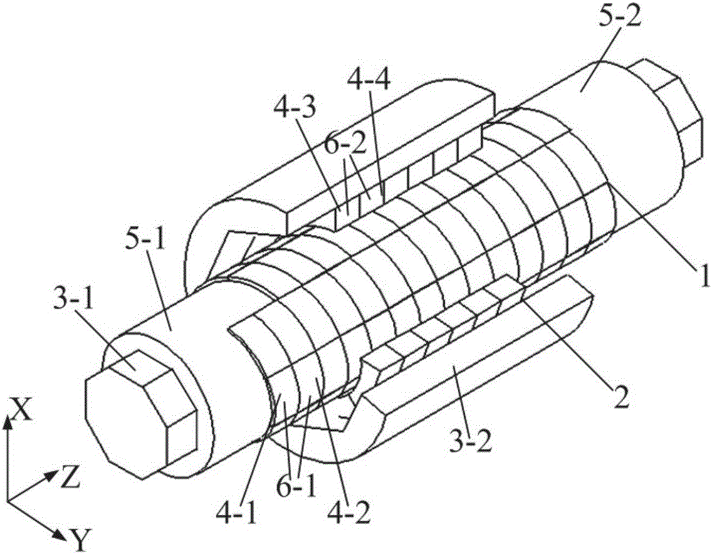

Image

  • Surface-mounted magnetic lead screw and processing method thereof
  • Surface-mounted magnetic lead screw and processing method thereof
  • Surface-mounted magnetic lead screw and processing method thereof

Examples


Embodiment

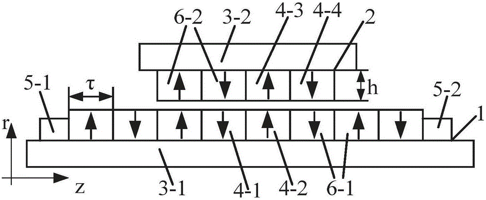
[0063] As a specific embodiment of the present invention, the present invention will be described below in conjunction with the accompanying drawings, as figure 1 with figure 2 As shown, the present invention is a surface-mounted magnetic screw and a processing method thereof, comprising a magnetic screw 1 and a magnetic nut 2 coaxial with an air gap therebetween. The magnetic nut 2 is empty sleeved outside the magnetic screw mandrel 1. The magnetic nut 2 rotates along the Z axis, and according to the working principle of the magnetic screw, the magnetic screw 1 moves linearly along the Z axis. Therefore, the axial length of the magnetic nut 2 is smaller than the axial length of the magnetic screw 1, and the specific size is determined according to the required characteristics of the magnetic screw.

[0064] The magnetic screw 1 is composed of a first permanent magnet a4-1, a first permanent magnet b4-2, an electrical iron rod 3-1, a limiter a5-1, and a limiter b5-2. Such ...


PUM


Abstract

The invention discloses a surface-mounted magnetic lead screw and a processing method thereof, and belongs to the field of magnetic lead screws. The magnetic lead screw comprises segmented permanent magnets, an electric iron rod and limiters. A magnetic nut comprises segmented permanent magnets and an electric iron ring. In the magnetic lead screw, the segmented permanent magnets are mounted on the outer surface of the electric iron rod; and in the magnetic nut, the segmented permanent magnets are mounted on the inner surface of the electric iron ring. The method comprises the following steps of leveling the inner diameters of the segmented permanent magnets of the magnetic lead screw; turning the outer surface of the electric iron rod to form the electric iron rod of which the axial section is a regular polygon according to the size of the segmented permanent magnets and simultaneously installing the limiters at the end parts of the electric iron rod; and leveling the outer diameters of the segmented permanent magnets of the magnetic nut, and drilling the electric iron ring to form a through hole of which the axial section is a regular polygon according to the size of the segmented permanent magnets. Through cooperation of the permanent magnets and a ferromagnetic material, the processing difficulty of a spiral permanent magnet and the assembly difficulty of the magnetic lead screw can be effectively reduced; and the thrust density and the mechanical strength are improved.

Description

technical field [0001] The invention relates to a manufacturing technology of a high-thrust density magnetic screw, in particular to an equivalent technology of a spiral magnetic circuit and a method for assembling the magnetic screw. Background technique [0002] The research on the magnetic screw actuation system is still in its infancy at home and abroad. The magnetic screw has the characteristics of high thrust density, no contact friction, and simple maintenance. It can convert rotary motion into linear motion through magnetic field coupling, and vice versa. Therefore, it has good application prospects in many occasions such as aerospace, marine power generation, artificial heart and other fields. At present, most of the research on magnetic screw is surface-mounted magnetic screw with permanent magnets radially magnetized and alternating N and S poles. However, this structure has the problems of magnetic screw assembly and helical permanent magnet processing. [0003...

Claims


Application Information

Patent Timeline
Patent Type & Authority Applications(China)
IPC IPC(8): H02K49/10H02K15/00
CPCH02K15/00H02K49/102H02K49/10
Inventor 赵文祥凌志健吉敬华刘国海徐媚媚胡德水
Owner JIANGSU UNIV
Learn More