Direct current output switch circuit

A switching circuit, DC output technology, applied in circuit devices, battery circuit devices, current collectors, etc., can solve the problems such as the failure of the relay withstand voltage to be more than 1300V, the large current of the battery pack, and the increase of safety hazards, so as to save costs. , The effect of preventing current backflow and improving production efficiency

Inactive Publication Date: 2016-07-06
上海航天智能装备有限公司
View PDF3 Cites 1 Cited by
  • Summary
  • Abstract
  • Description
  • Claims
  • Application Information

AI Technical Summary

Problems solved by technology

In this way, when the voltage of the battery pack is higher than that of the DC charger, the battery pack will reversely charge the capacitor inside the charger, which will easily cause the charger to fail for a long time.
Especially when the DC output circuit is connected to the battery pack, it will cause the battery pack to generate a huge current or arc in an instant, which may cause a fire in severe cases. Therefore, it is necessary to add an anti-backfeed device at the DC output end to prevent such hidden dangers
[0003] When the rated current input by the DC bus bar is 30A and the DC voltage is 1300V, the anti-reverse diode needs to withstand a voltage of more than 1500V and the overcurrent capacity is greater than 30A. If the anti-reverse device is not suitable, it will increase safety hazards; For the switching device of the output circuit, it is necessary to consider that the single withstand voltage of the existing relay cannot exceed 1300V

Method used


Image

  • Direct current output switch circuit
  • Direct current output switch circuit

Examples


Embodiment Construction

[0021] The present invention will be described in detail below in conjunction with the accompanying drawings and specific embodiments. This embodiment is carried out on the premise of the technical solution of the present invention, and detailed implementation and specific operation process are given, but the protection scope of the present invention is not limited to the following embodiments.

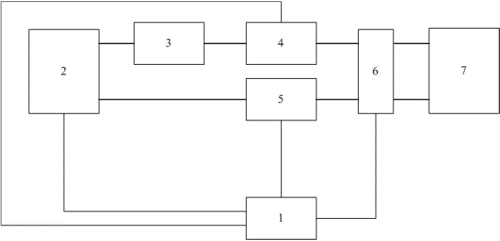
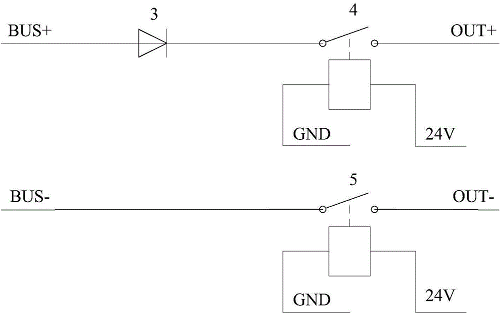
[0022] like figure 1 , figure 2 As shown, a DC output switching circuit includes a busbar (BUS) and an output interface (OUT) connected to the battery pack 7, the rated current of the busbar is 30A, the DC voltage is 1300V, and an anti-reverse 二 Pole tube 3, DC relay 2, first relay 4, second relay 5, voltage detector 6 and main controller 1, DC relay 2 is set at the input end of the bus bar, and the positive pole of the anti-reverse diode 3 is connected to the positive pole and negative pole of the bus bar Connect one end of the normally open point of the first relay 4, the other e...


PUM


Abstract

The invention relates to a direct current output switch circuit, comprising a bus and an output interface in connection with a battery, and also comprising a direct current relay, an anti-reverse diode, a first relay, a second relay, a voltage detector and a master control device. The direct current relay is arranged at the input terminal of the bus; the positive electrode of the anti-reverse diode is in connection with the positive electrode of the bus, and the negative electrode is in connection with one end of a normally open point of the first relay; the other end of the normally open point of the first relay is in connection with the positive electrode of the output interface; one end of a normally open point of a second relay is in connection with the negative electrode of the bus, and the other end of the normally open point is in connection with the negative electrode of the output interface; the voltage detector is in parallel connection between the positive electrode and negative electrode of the output interface; the master control device is in connection with the direct current relay, the first relay, the second relay and the voltage detector. Compared with the prior art, the direct current output switch circuit has the advantages of high safety and stability, great controllability, low cost, wide applicability, etc., and is suitable for connecting with a bus having the rated current of 30 A and direct voltage of 1300V.

Description

technical field [0001] The invention relates to a switch circuit, in particular to a DC output switch circuit. Background technique [0002] In recent years, the use of direct current to charge battery packs has become more and more widely used. When the existing DC output circuit charges the battery pack, its output positive and negative busbars need to be connected with the battery pack. In this way, when the voltage of the battery pack is higher than that of the DC charger, the battery pack will reversely charge the capacitor inside the charger, which will easily cause the charger to fail for a long time. Especially when the DC output circuit is connected to the battery pack, it will cause the battery pack to generate a huge current or arc in an instant. In severe cases, it may cause a fire. Therefore, it is necessary to add an anti-backfeed device at the DC output end to prevent such hidden dangers. [0003] When the rated current of the DC bus input is 30A and the DC ...

Claims


Application Information

Patent Timeline
Patent Type & Authority Applications(China)
IPC IPC(8): H02J7/00
Inventor 朱云阁赵宜鹏
Owner 上海航天智能装备有限公司
Why Eureka
Try Eureka