Overhead power line connection wire clamp
A technology for power lines and connecting wires, which is applied in the direction of circuits, conductive connections, and electrical component connections. It can solve problems such as poor firmness and easy loosening, and achieve the effects of reducing vibration, reasonable center of gravity distribution, and ensuring stability and reliability.
- Summary
- Abstract
- Description
- Claims
- Application Information
AI Technical Summary
Problems solved by technology
Method used
Image

Examples
Embodiment 1
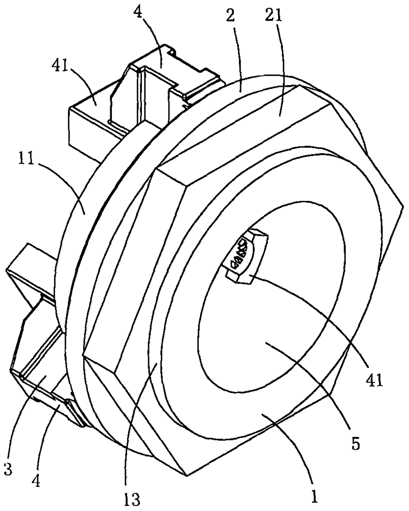
[0026] The present embodiment is a kind of connecting clip of overhead power line, see Figure 1 to Figure 7 As shown, it includes a base body 1, a flat nut 2 and a set of pressure jaw assembly 3, the pressure jaw assembly includes three pressure jaws 4; the base body is provided with a slide tube 11, a radial guide limit hole 12 arranged on the slide tube and The block 13 that is arranged on the outer peripheral wall of the slide tube protrudes outward along the radial direction of the slide tube; the radial guide limit hole penetrates the tube wall of the slide tube along the radial direction of the base slide tube; the shape of the block is ring-shaped, and the block It is located at one end of the base sliding tube in the axial direction, and the radial guide limiting hole 12 is located at the other end of the base sliding tube in the axial direction;
[0027] The quantity of radial guide limit hole 12 is the same as the quantity of pressure jaw 4, also is three; Sliding ...
Embodiment 2
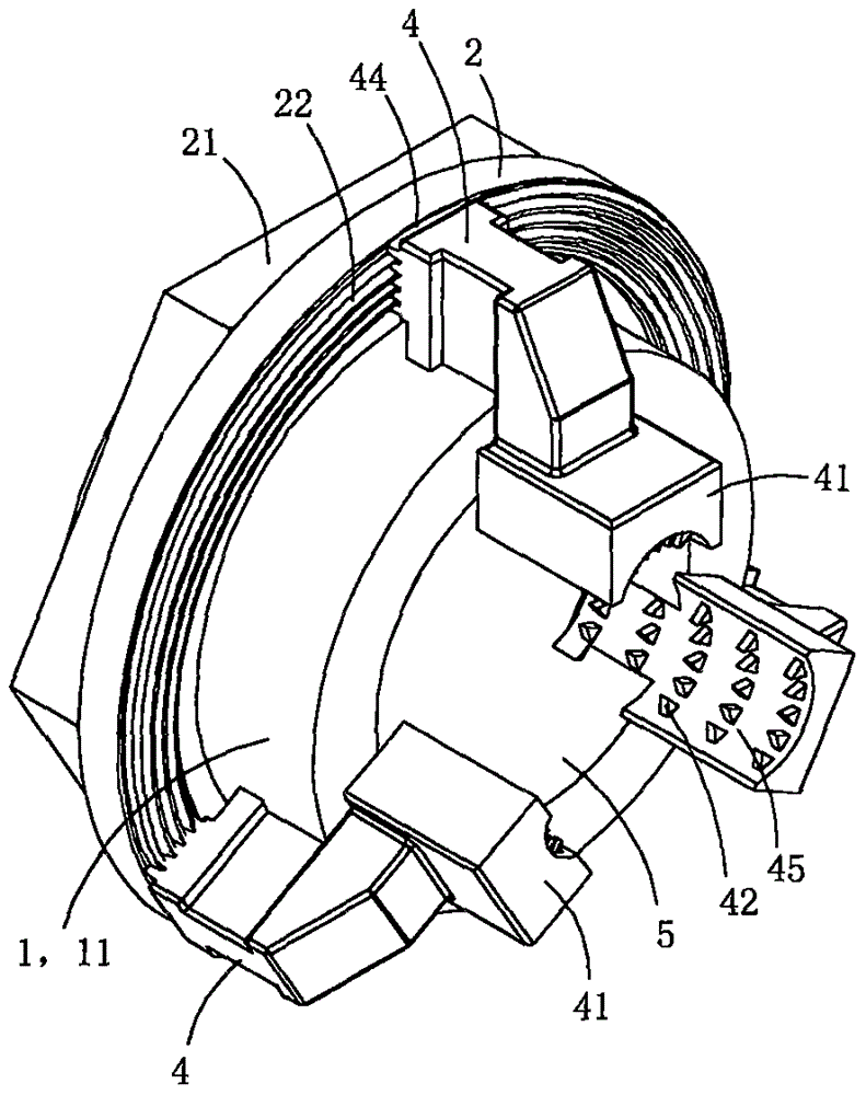
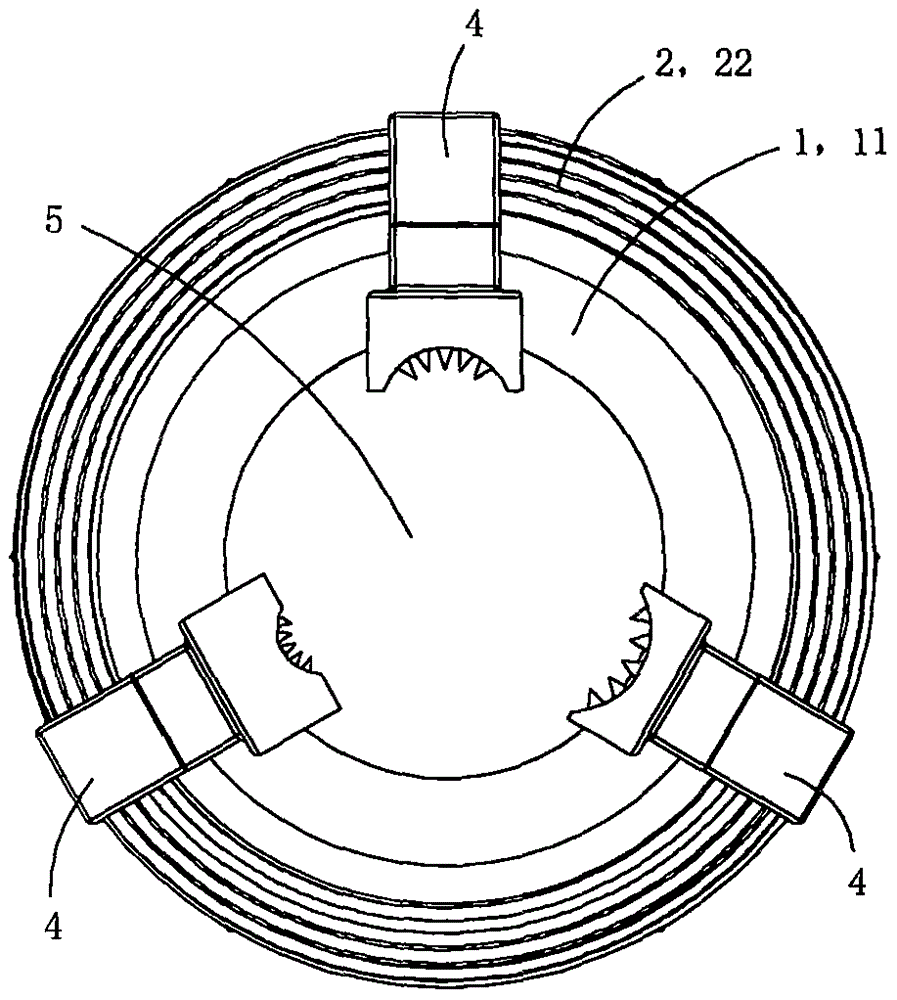
[0039] This embodiment is basically the same as Embodiment 1, the difference is: see Figure 8 to Figure 14 As shown, this embodiment also includes a mandrel 6 located in the lumen of the base slide tube; three arc-shaped clamping grooves 61 are arranged on the outer peripheral wall of the mandrel 6 along the central axis of the base tube, and each arc-shaped clamping groove is provided with Multiple punctures; each arc-shaped clamping groove is set opposite to the arc-shaped groove 45 on the inner wall of the corresponding one of the pressing jaws, and each arc-shaped clamping groove and the corresponding one arc-shaped groove are clamped to form a wire clamping hole 5, so this embodiment forms a total of Three clamping holes 5 can be used to clamp three cables at the same time;
[0040] The outer peripheral wall of the mandrel is provided with three supporting and positioning convex plates 62 protruding radially along the base sliding tube, and the inner peripheral wall of t...
Embodiment 3
[0042] This embodiment is basically the same as Embodiment 1, the difference is: see Figure 15 As shown, the length of the base slide tube in this embodiment is slightly longer, and a voltage transformer 7 is sheathed and fixed on the outer peripheral wall of the base slide tube. Since the power cable passes through the lumen of the base slide tube, the voltage transformer The device can obtain a lower induced voltage through induction, which can be used as a power supply for auxiliary equipment. For example, a camera with a wireless transceiver unit, a temperature sensor, a humidity sensor or a lightning strike counter and other auxiliary equipment can be fixedly installed on the lower part of the base slide tube to monitor the environment around the clamp in real time, and the real-time The information is sent to the remote host to provide basic data for the intelligentization of power lines; and the voltage transformer in this embodiment provides stable and sustainable pow...
PUM
 Abstract
Description
Claims
Application Information
 - R&D
- Intellectual Property
- Life Sciences
- Materials
- Tech Scout
- Unparalleled Data Quality
- Higher Quality Content
- 60% Fewer Hallucinations
Browse by: Latest US Patents, China's latest patents, Technical Efficacy Thesaurus, Application Domain, Technology Topic, Popular Technical Reports.
© 2025 PatSnap. All rights reserved.Legal|Privacy policy|Modern Slavery Act Transparency Statement|Sitemap|About US| Contact US: help@patsnap.com