Superconducting magnet apparatus in magnetic resonance imaging system
A technology for magnetic resonance imaging and superconducting magnets, which is applied in superconducting magnets/coils, measuring devices, magnetic objects, etc., and can solve problems such as coil displacement, magnet quench, and unstable support structures.
- Summary
- Abstract
- Description
- Claims
- Application Information
AI Technical Summary
Problems solved by technology
Method used
Image
Examples
Embodiment 1
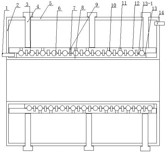
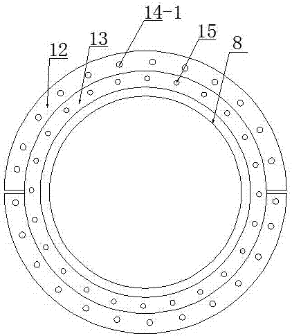
[0029] Embodiment 1: A superconducting magnet device in a magnetic resonance imaging system, including an inner cylinder 8 and an outer cylinder 5 sleeved on the inner cylinder 8, the inner cylinder is provided with an annular sleeve 13, and the annular sleeve There is an inner wire groove 6 on the top, and the wire of the magnet is wound in the inner wire groove. The annular sleeve is provided with two arc clips 12, and the arc clip is provided with the inner wire groove. The matching upper wire groove 10, the annular sleeve is provided with several through holes 15 that pass through the inner wire groove wall 13-1 and communicate with the inner wire groove, the sleeve between the inner wire grooves Several guide grooves 7 are provided on the barrel, and several upper guide holes 11 passing through the arc clamp body and connecting with the upper wire groove are provided on the arc clamp body, and the arc clamp body is provided with There are several upper guide holes 9 commu...
Embodiment 2
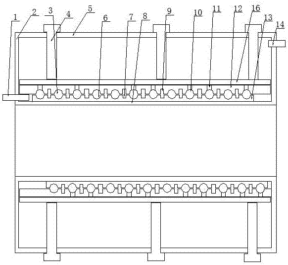
[0040] Embodiment 2: A superconducting magnet device in a magnetic resonance imaging system, comprising an inner cylinder 8 and an outer cylinder 5 set on the inner cylinder 8, the inner cylinder is provided with an annular sleeve 13, and the annular sleeve There is an inner wire groove 6 on the top, and the wire of the magnet is wound in the inner wire groove, and the wire is wound into a circle. Two arc clips 12 are arranged on the annular sleeve, and There is an upper wire groove 10 that matches the inner wire groove, and the annular sleeve is provided with several through holes 15 that pass through the wall of the inner wire groove and communicate with the inner wire groove. The sleeve in between is provided with several guide grooves 7, and the arc clip body is provided with several upper guide holes 11 passing through the clip body and communicating with the upper conductor groove, and the arc clip body is provided with There are several upper guide holes 9 communicating...
Embodiment 3
[0054] Embodiment 3: The difference between it and Embodiment 2 is that the arc-shaped clip body is preferably a semicircular clip body, and the clip body is provided with threads, and the arc-shaped clip body is threadedly connected with a threaded sleeve. There are several ventilation holes, the ventilation holes communicate with the through holes on the clip body, the pressing mechanism is pressed on the threaded sleeve, and the coil is fixed more firmly. After adopting the above-mentioned improvement of embodiment 2, it is not easy to use In the actual test process, the maximum allowable current of the wire is not exceeded. The normal current is 500A, and the current is increased to 863A. After 1 year of operation, there is no quench fault. At the same time, the wire has not occurred after disassembly and inspection Displacement, the structure of the prior art is used in the test process, such as the patent disclosed in CN103887035B, the normal power supply is 500A, and the...
PUM
 Abstract
Description
Claims
Application Information
 - R&D Engineer
- R&D Manager
- IP Professional
- Industry Leading Data Capabilities
- Powerful AI technology
- Patent DNA Extraction
Browse by: Latest US Patents, China's latest patents, Technical Efficacy Thesaurus, Application Domain, Technology Topic, Popular Technical Reports.
© 2024 PatSnap. All rights reserved.Legal|Privacy policy|Modern Slavery Act Transparency Statement|Sitemap|About US| Contact US: help@patsnap.com


