
Low-profile lens antenna capable of realizing wide-angle scanning

A lens antenna, wide-angle scanning technology, applied to antennas, electrical components, etc., can solve the problems of high profile, high profile, and high cost of the whole machine, and achieve the effects of easy lens assembly, high design flexibility, and good electrical performance.

Inactive Publication Date: 2016-07-06
NO 54 INST OF CHINA ELECTRONICS SCI & TECH GRP
View PDF6 Cites 34 Cited by
  • Summary
  • Abstract
  • Description
  • Claims
  • Application Information

AI Technical Summary

Problems solved by technology

[0003] 1. The parabolic reflector antenna has the characteristics of high gain, and the servo mechanism is used to realize the beam scanning, but the profile of the whole machine is high, and the conformal design cannot be realized
[0004] 2. The profile of the phased array antenna is low, and components such as phase shifting devices are used to achieve high-gain transmission and beam scanning, and its radiation array can be designed conformally, but a large number of phase shifters and complex control circuits lead to high cost and difficulty in heat dissipation etc., this problem is especially serious for large-aperture phased array antennas
[0005] 3. Ordinary lens antennas (such as Loper lens and homogeneous medium lens) can realize high-gain signal transmission and beam scanning by using a servo mechanism to control the feed. However, the medium forming process of the Loper lens is difficult and the strength is poor. The Loper lens and the Homogeneous dielectric lenses all have the disadvantages of high profile, heavy weight, and difficulty in conformal shape, especially they cannot be used on airborne or missile-borne platforms

Method used


Image

  • Low-profile lens antenna capable of realizing wide-angle scanning
  • Low-profile lens antenna capable of realizing wide-angle scanning
  • Low-profile lens antenna capable of realizing wide-angle scanning

Examples


Embodiment Construction

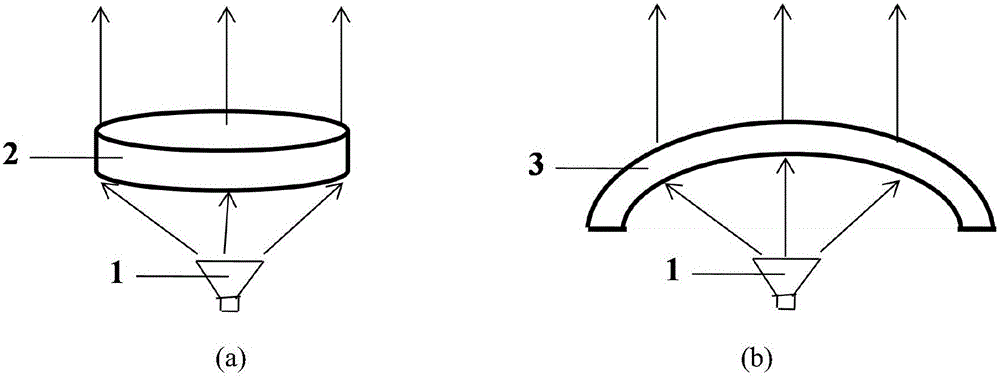
[0023] The low-profile lens antenna of the present invention comprises a feed source 1 and a circular plate lens 2 or a curved lens 3, and the phase center of the feed source 1 is positioned at the focal point of the lens 2 or lens 3, such as figure 1 shown. Flat lens 2 and curved lens 3 are especially suitable for mobile platforms that require conformality.

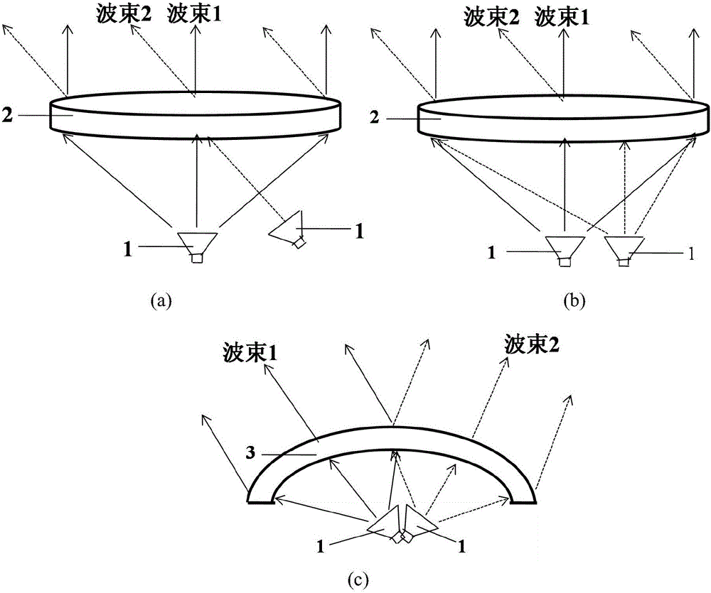
[0024] The scanning working principle of the lens antenna of the present invention is as follows: figure 2 shown. The beam scanning is realized by mechanically controlling the movement of the feed source, and the movement method of the feed source includes such as figure 2 The two-dimensional surface movement shown in a, such as figure 2 The two-dimensional plane movement shown in b, such as figure 2 The feed rotation shown in c, etc. In order to obtain high-efficiency wide-angle scanning performance, the feed can adopt one or more of the above moving methods.

[0025] Placing multiple feeds under the lens can ...


PUM


Abstract

The invention relates to a low-profile lens antenna capable of realizing wide-angle scanning. The lens antenna comprises a lens and a feed source positioned on the focal plane of the lens; beam scanning and tracking can be realized by mechanical control on the feed source; the lens has an electromagnetic wave focusing function, and the appearance of the lens can be flat-plate-shaped or curved-surface-shaped, and conformal design with a carrier platform can be realized; the effective dielectric constant distribution characteristic of the lens is that the effective dielectric constants are decreased from the center to the edges along the horizontal and longitudinal directions; the regulation and control on the effective dielectric constants can be realized by changing the structure or dimensions of the metamaterial units; and the assembling and preparation of the lens at a low cost is realized by multiple metamaterial panels in a stacked manner. The low-profile lens antenna has the characteristics of broadband, high gain, low profile, easy conformal property and the like, and is particularly suitable for high-gain conformal vehicle-mounted or missile-borne platforms in the fields of communication measurement and control, and the like.

Description

technical field [0001] The invention relates to a low-profile lens antenna capable of wide-angle scanning, which has the characteristics of wide frequency band, high gain, low profile, and easy conformality, and is especially suitable for airborne or missile-borne applications requiring high-gain conformality in the fields of communication measurement and control, etc. platform. Background technique [0002] In the field of communication measurement and control, there are mainly the following types of antennas that can achieve high gain and beam scanning, but they all have some defects in performance. [0003] 1. The parabolic reflector antenna has the characteristics of high gain, and the servo mechanism is used to realize the beam scanning, but the profile of the whole machine is high, and the conformal design cannot be realized. [0004] 2. The profile of the phased array antenna is low, and components such as phase shifting devices are used to achieve high-gain transmis...

Claims


Application Information

Patent Timeline
Patent Type & Authority Applications(China)
IPC IPC(8): H01Q15/00H01Q15/02H01Q19/06
CPCH01Q15/0086H01Q15/02H01Q19/06
Inventor 贾丹何应然丁宁杨杨董长胜张文静杜彪
Owner NO 54 INST OF CHINA ELECTRONICS SCI & TECH GRP
Learn More