
Combined filter employing ceramic resonator grooving and coupling mode

A ceramic resonator, coupling technology, applied in waveguide devices, electrical components, circuits, etc., can solve the problems of large insertion loss, poor suppression, poor second harmonic performance, etc., to achieve low loss, suppression of second harmonic wave effect

Inactive Publication Date: 2016-07-06
JIAXING GLEAD ELECTRONICS CO LTD
View PDF4 Cites 23 Cited by
  • Summary
  • Abstract
  • Description
  • Claims
  • Application Information

AI Technical Summary

Problems solved by technology

[0004] The monolithic filter is formed by a complete dielectric block. This type of filter has better near-end suppression performance, but poor second harmonic performance.
[0005] The combined filter is composed of multiple dielectric coaxial resonators, lead pins and capacitors. This type of filter has better second harmonic performance, but the insertion loss is too large and the near-end rejection is poor.

Method used


Image

  • Combined filter employing ceramic resonator grooving and coupling mode
  • Combined filter employing ceramic resonator grooving and coupling mode
  • Combined filter employing ceramic resonator grooving and coupling mode

Examples


Embodiment Construction

[0027] The specific implementation manner of the present invention will be described in detail below in conjunction with the accompanying drawings.

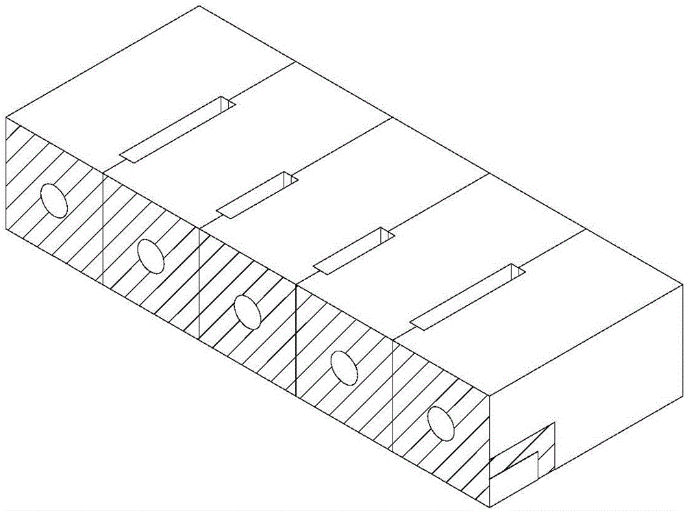
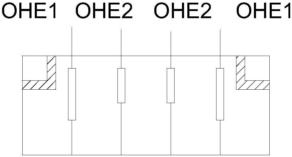
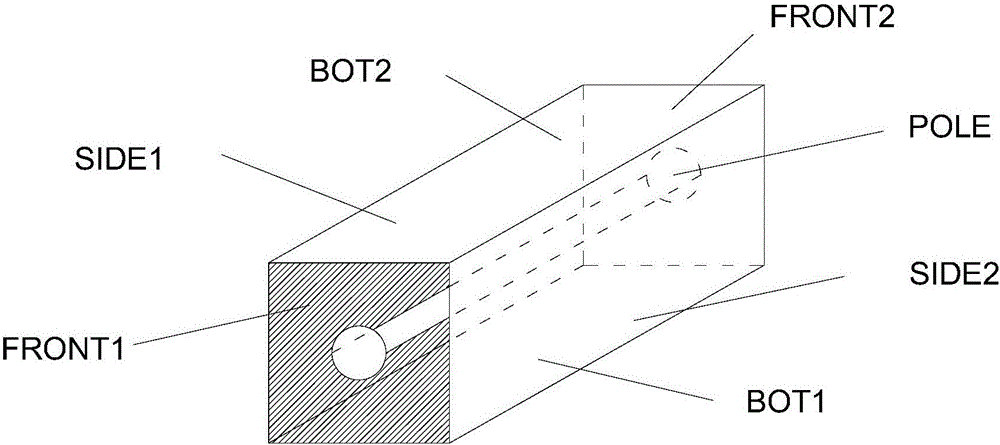
[0028] Such as figure 1 The combined filter shown in the ceramic resonator slot coupling method includes a first resonator, a second resonator, a third resonator, a fourth resonator and a fifth resonator. Such as image 3 As shown, the top surface FRONT1 of the five coaxial resonators is an open surface without a conductive layer and is in an insulating state; the two sides SIDE1 and SIDE2 are metallized and covered with a conductive layer; the upper surface BOT1 and the lower surface The surface of BOT2 is metallized and covered with a conductive layer, of which the surface of BOT1 is used as the ground plane; the surface of the tail end FRONT2 is metallized and covered with a conductive layer; the central axis of the 5 coaxial resonators is provided with shaft holes and shaft holes The POLE on the inner wall of the hole is tr...


PUM


Abstract

The invention relates to the field of microwave communication, in particular to a combined filter. According to a combined filter employing a ceramic resonator grooving and coupling mode, each coaxial resonator comprises an open front-end surface of a non-conductive material and the other five surfaces are covered with a conductive material to form a conductive layer; two coaxial resonators at the outmost side comprise electrode surfaces of a signal input attenuator and a signal output attenuator; and coupling grooves are formed between cavity bodies of the coaxial resonators to form coupling of the filter. Adjustment on specific performance parameters of the filter is achieved through adjustment on the lengths of the coaxial resonators and the coupling grooves. The filter has the advantages of low loss and high inhibition; and second harmonics of a product are greatly improved.

Description

technical field [0001] The invention relates to the field of microwave communication, in particular to a combined filter. Background technique [0002] The dielectric filter will form a passband to pass the signal that needs to pass, and suppress the unwanted signal frequency band so that it will not pass. Due to the presence of capacitors and lead pins in the traditional combined filter, the loss will increase accordingly. At the same time, the traditional filter will form a second harmonic at the place where the frequency is doubled, so that it is very suppressed at the place where the center frequency is doubled. Poor, even form a secondary passband to prevent the signal from passing. [0003] The current ceramic dielectric filters are generally divided into two categories, single type and combined type. [0004] The monolithic type means that the filter is formed by a complete dielectric block. This type of filter has better near-end suppression performance, but poor s...

Claims


Application Information

Patent Timeline
IPC IPC(8): H01P1/20
CPCH01P1/20
Inventor 邵国云张元元胡元云吴飞甲尤源
Owner JIAXING GLEAD ELECTRONICS CO LTD
Learn More