A tandem toll queue management system for toll roads
A queue management system and tandem technology, applied in the toll system field of toll roads, can solve problems such as cumbersome, dangerous, and affecting vehicle traffic efficiency, and achieve the effect of avoiding missed collection and strong adaptability
- Summary
- Abstract
- Description
- Claims
- Application Information
AI Technical Summary
Problems solved by technology
Method used
Image
Examples
Embodiment 1
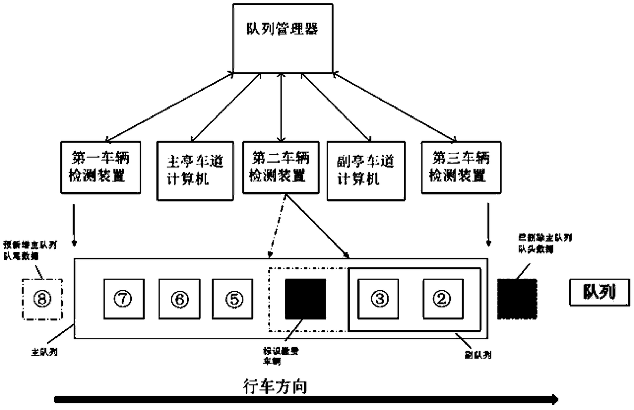
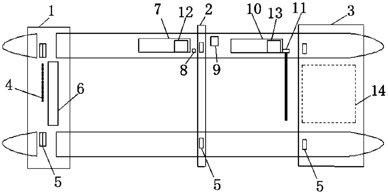
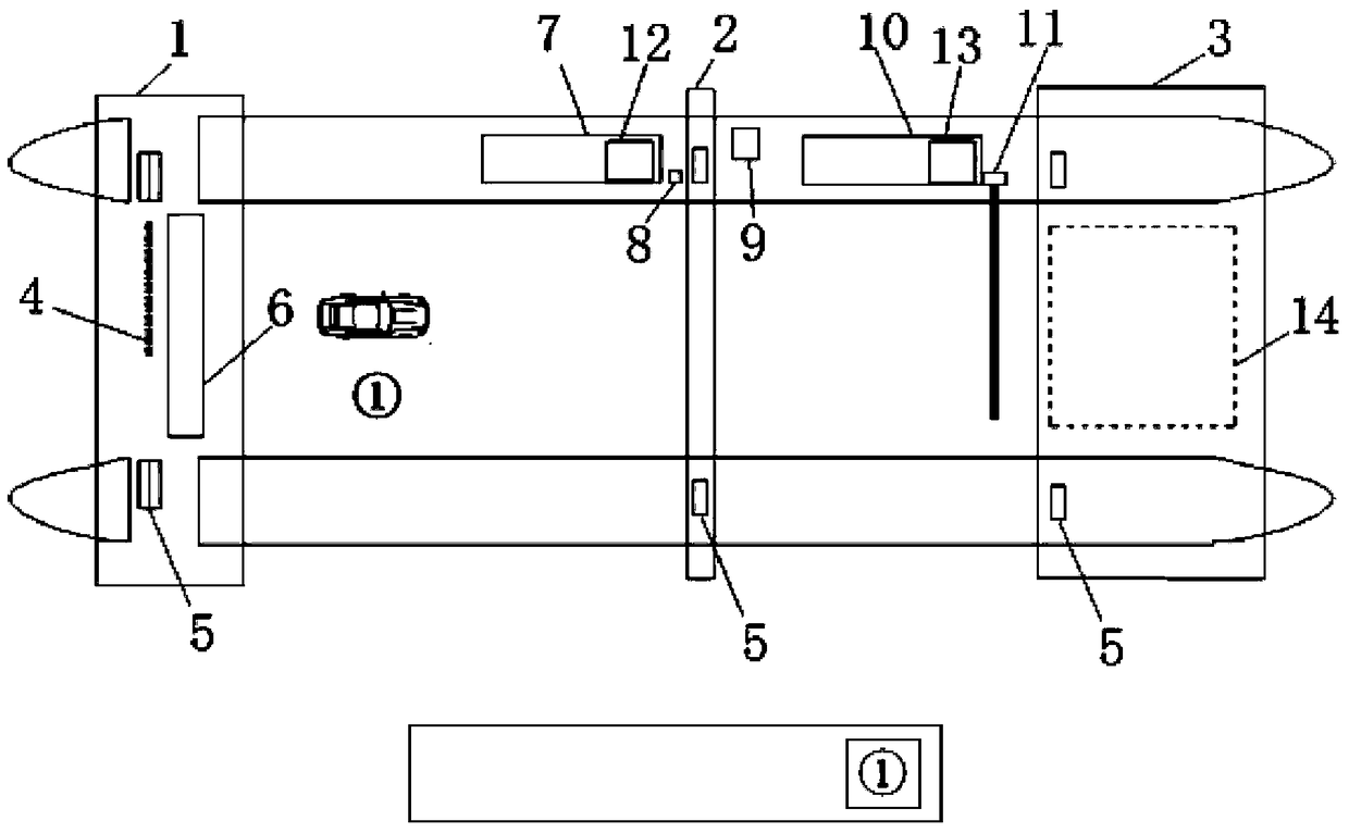
[0041] Such as figure 1 with figure 2 As shown, a toll road tandem toll queue management system includes a first vehicle detection device 1 located at the entrance lane or exit lane island of a toll road toll station, and an information induction device located behind the main toll booth 7 or card issuing machine. Screen 8 and the second vehicle detection device 2, the electric railing 11 and the 3rd vehicle detection device 3 that are located at the compound toll booth 10 or the compound card issuing machine rear also include queue manager 9, and described queue manager 9 is arranged for According to the data obtained by the first vehicle detection device 1, the second vehicle detection device 2, and the third vehicle detection device 3, the vehicle charging data queue is kept first-in-first-out and contains the main and auxiliary queues, and can switch between different charging modes and modes. Accurately identify the data measured by the first vehicle detector 1 of the v...
Embodiment 2
[0053] In order to save costs, this embodiment is the same as Embodiment 1 except for the following features: the main and secondary queues are managed in series, and the main queue is vehicles passing through the first vehicle detection device 1 and not leaving The first-in-first-out vehicle model and weight data queue formed by the second vehicle detection device 2; And the weight data queue. The head data of the main queue is the model and weight data corresponding to the vehicles at the main toll booth 7, and the head data of the auxiliary queue is the model and weight data corresponding to the vehicles at the 10 compound toll booths.
[0054] When the vehicle passes the first vehicle detection device 1, a piece of vehicle type and weight data detected by the first vehicle detection device 1 is added at the tail of the main queue; when the vehicle passes the first vehicle detection device 1, a vehicle at the tail of the main queue is deleted. vehicle type and weight data;...
Embodiment 3
[0057] In order to save costs, this embodiment is the same as Embodiment 1 except for the following features: the second vehicle detection device 2 is a combination of a single light curtain and 2-4 or more wheel axle sensors 4 at a distance of 0.1m to 1m. In combination, the direction of vehicle entry is determined only by the wheel axle sensor 4 .
PUM
 Abstract
Description
Claims
Application Information
 - R&D Engineer
- R&D Manager
- IP Professional
- Industry Leading Data Capabilities
- Powerful AI technology
- Patent DNA Extraction
Browse by: Latest US Patents, China's latest patents, Technical Efficacy Thesaurus, Application Domain, Technology Topic, Popular Technical Reports.
© 2024 PatSnap. All rights reserved.Legal|Privacy policy|Modern Slavery Act Transparency Statement|Sitemap|About US| Contact US: help@patsnap.com


