
A valve automatic testing equipment

A technology for automatic testing equipment and valves, which is used in fluid tightness testing, machine/structural component testing, and measuring devices. Convenience, good action consistency and high efficiency

Active Publication Date: 2018-10-30
辛集市邑阔天然气有限公司
View PDF14 Cites 2 Cited by
  • Summary
  • Abstract
  • Description
  • Claims
  • Application Information

AI Technical Summary

Problems solved by technology

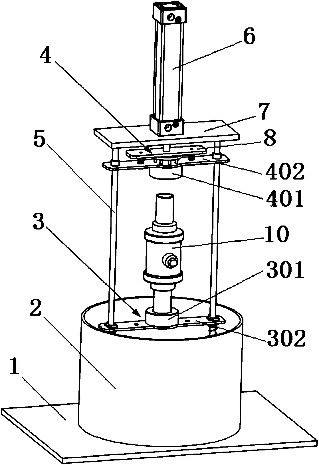
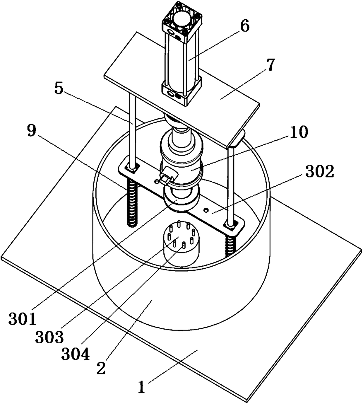
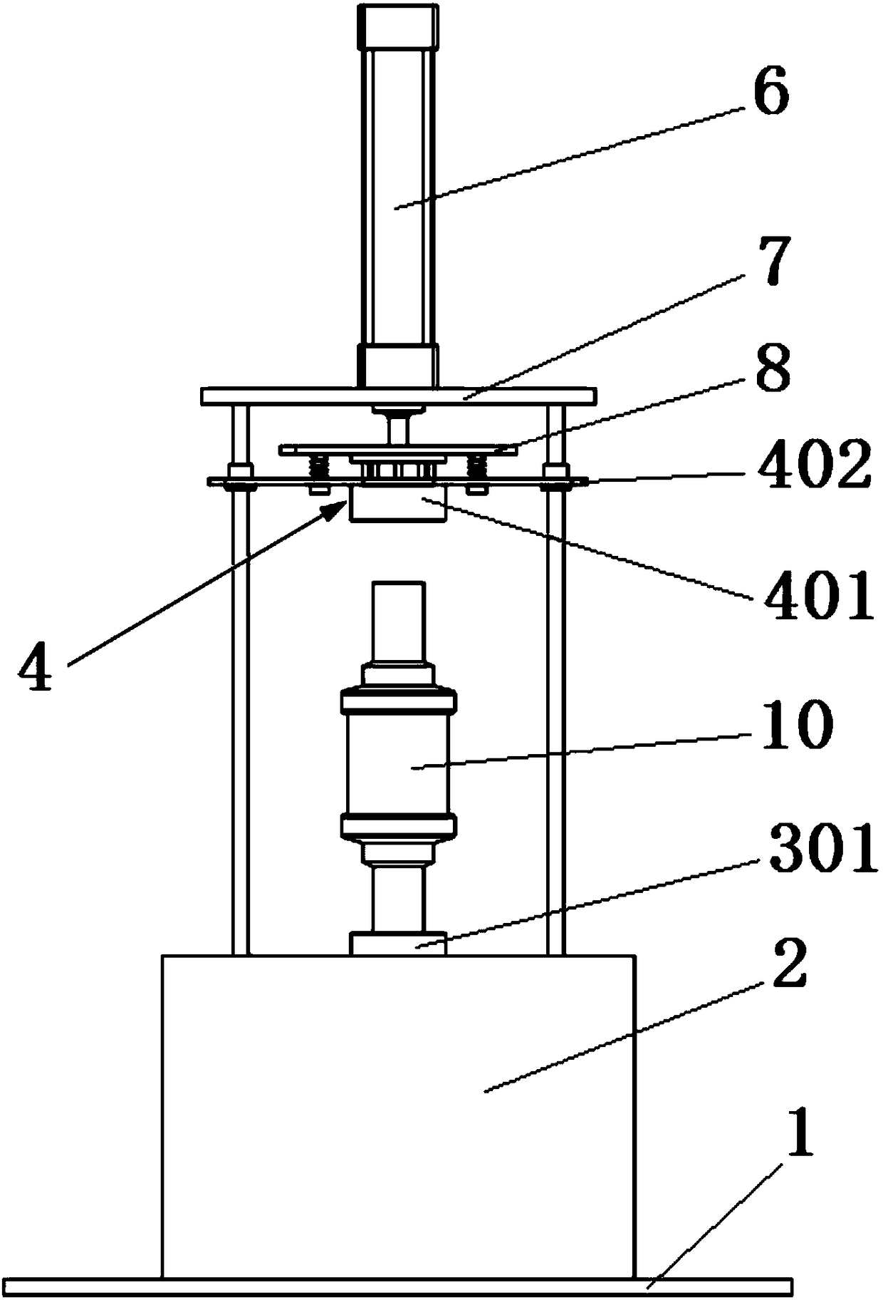
[0004] In order to solve the problems of inconvenient clamping, low efficiency, manpower consumption and low degree of automation in the current valve sealing performance testing method, the present invention proposes a valve sealing performance testing device with high testing efficiency, convenient clamping and high automation

Method used


Image

  • A valve automatic testing equipment
  • A valve automatic testing equipment
  • A valve automatic testing equipment

Examples


Embodiment Construction

[0026] The present invention will be further described below in conjunction with the accompanying drawings and specific embodiments.

[0027] A valve automatic testing equipment, see figure 1 , figure 2 , image 3 , including a base 1 and a water tank 2 arranged on the base 1, two polished rods 5 of equal height are arranged in the described water tank 2, the two polished rods 5 are vertically arranged and the upper ends of the polished rods 5 extend out of the water tank 2, the water tank 2. There is a fixed plate 7 connected to the two polished rods 5 above. An upper sealing mechanism 4 for sealing the upper end of the valve 10 and a lower sealing mechanism 4 for sealing the lower end of the valve 10 are arranged between the fixed plate 7 and the bottom of the water tank 2. Mechanism 3, the fixed plate 7 is provided with a cylinder 6 for driving the upper sealing mechanism 4, the cylinder body of the cylinder 6 is fixed on the fixed plate 7 upside down, and the piston rod...


PUM


Abstract

The invention discloses automatic valve test equipment, and relates to the field of tests of sealing properties of valves. The automatic valve test equipment comprises a base and a water tank arranged on the base, wherein two polish rods are vertically arranged in the water tank, and the upper ends of the polish rods extend out of the water tank; a fixed plate connected with the two polish rods is arranged above the water tank; an upper sealing mechanism for sealing the upper end of the valve and a lower sealing mechanism for sealing the lower end of the valve are arranged between the fixed plate and the bottom of the water tank; a cylinder for driving the upper sealing mechanism is arranged on the fixed plate. The valve sealing property test equipment aims at solving the problems that an existing valve sealing property test method is inconvenient for clamping, low in efficiency and low in automation degree and costs much labor, and is high in test efficiency, convenient for clamping and high in automation degree.

Description

technical field [0001] The invention relates to the field of sealing performance testing machines, in particular to automatic sealing performance testing equipment for valves. Background technique [0002] Valves are commonly used opening and closing parts for gas or liquid circulation. They are generally used in two important industries: gas pipeline network and water conservancy transportation. Therefore, leak detection and torque testing are required before leaving the factory, otherwise there will be greater safety hazards. [0003] In the existing technology, the automation degree of the valve test method is not high. When testing the sealing performance, the gasket is usually placed outside the two ends of the valve, and the two ends of the valve are clamped by a force-applying device such as a jack or a hydraulic cylinder, so that the gasket Form a seal with the two ends of the valve, then put the whole sealed valve into the water manually, and then pass compressed ga...

Claims


Application Information

Patent Timeline
Patent Type & Authority Patents(China)
IPC IPC(8): G01M3/08
CPCG01M3/086
Inventor 宣月罗
Owner 辛集市邑阔天然气有限公司
Learn More