Plate type heat exchanger with vaporizing space for gas-liquid separating

A plate heat exchanger and space technology, applied in heat exchange equipment, indirect heat exchangers, heat exchanger types, etc., can solve problems such as larger scale, larger system space, and increased system pressure loss

Active Publication Date: 2016-07-06
KOREA INST OF ENERGY RES
View PDF5 Cites 2 Cited by
  • Summary
  • Abstract
  • Description
  • Claims
  • Application Information

AI Technical Summary

Problems solved by technology

[0007] The structure of this circulation system has the following problems, that is, the time and cost consumed for the manufacture of the system are increased due to the inclusion of an additional gas-liquid separator, and the pressure loss of the system is increased.
[0008] And, since an additional gas-liquid separator is further included, there is also a problem that the process of the circulation system and the scale of the system itself become large, and a larger space for installing the system is required

Method used


Image

  • Plate type heat exchanger with vaporizing space for gas-liquid separating
  • Plate type heat exchanger with vaporizing space for gas-liquid separating
  • Plate type heat exchanger with vaporizing space for gas-liquid separating

Examples


no. 1 example

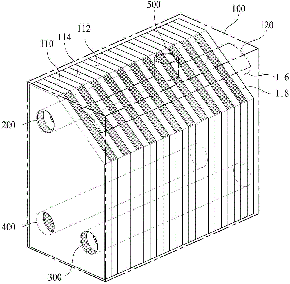
[0029] First, refer to figure 1 and figure 2 , the structure of the first embodiment of the plate heat exchanger according to the present invention will be described in detail.

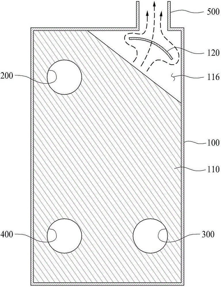
[0030] in, figure 1 is a drawing showing a first embodiment of a plate heat exchanger according to the present invention, figure 2 is a cross-sectional view of a first embodiment of a plate heat exchanger according to the present invention.

[0031] like figure 1 and figure 2 As shown, the plate heat exchanger according to the present invention may include a casing 100 , a first supply line 200 , a first outflow line 300 , a second supply line 400 and a second outflow line 500 .

[0032] The casing 100 is a structure that integrally surrounds various structures for performing heat exchange of the heat medium in the plate heat exchanger according to the present invention, and in this embodiment, may include a plurality of plates that are stacked and arranged at regular intervals in the front...

no. 2 example

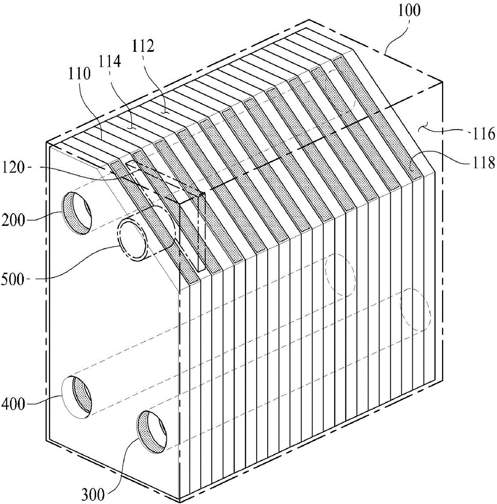
[0075] Next, refer to Figure 4 , the structure of the second embodiment of the plate heat exchanger according to the present invention will be described in detail.

[0076] in, Figure 4 is a drawing showing a second embodiment of the plate heat exchanger according to the present invention.

[0077] like Figure 4 As shown, the plate heat exchanger according to the present invention may include: plates 600 , a first supply line 700 , a first outflow line 800 , a second supply line 900 , a casing 1000 and a second outflow line 1100 .

[0078] Among them, the structures of the first supply line 700, the first outflow line 800, the second supply line 900 and the second outflow line 1100 and the above-mentioned first supply line 200 of the first embodiment of the plate heat exchanger according to the present invention, the first The structures of the outflow line 300 , the second supply line 400 and the second outflow line 500 are the same, and thus detailed descriptions there...


PUM


Abstract

The invention relates to a plate type heat exchanger which includes: a housing which includes a plurality of plate sheets which are formed by repetition of a first flow path which flows a first thermal medium and a second flow path which flows a second thermal medium, the first flow path and the second flow path being placed in an overlapping arrangement at a certain interval in a front and back direction, and vaporizing space being formed in the upper parts of the plate sheets, the second flow path being configured to form discharge holes which discharge the second thermal medium to the vaporizing space; a first supplying line which is configured to form a shape which penetrates the plurality of plate sheets so as to enable the first thermal medium to only flow to the first flow path; a first outflow line which is configured to form a shape which penetrates the plurality of plate sheets so as to recycle the first thermal medium which is subject to thermal exchange in the first flow path; a second supplying line which is configured to form a shape which penetrates the plurality of plate sheets so as to enable the second thermal medium to only flow to the second flow path; a second outflow line which is connected to the housing and discharges the second thermal medium in the vaporizing space.

Description

technical field [0001] The present invention relates to a plate heat exchanger, and more particularly, to a plate heat exchanger, which is not provided with an additional gas-liquid separator and can perform gas-liquid separation inside the heat exchanger . Background technique [0002] A heat exchanger is a device that changes the temperature and phase of the fluid by exchanging heat between different fluids. It has been widely used in various technical fields such as power generation and heating and cooling. [0003] In particular, since the heat exchange efficiency of the plate heat exchanger method is high and the volume and weight of the heat exchanger can be reduced, the development of related technologies is being actively carried out. [0004] Various circulation systems to which such heat exchangers are applied, such as power generation systems, etc., in which the fluid phase is to be changed, mainly include a process of converting a heat medium in a liquid state i...

Claims


Application Information

Patent Timeline
Patent Type & Authority Applications(China)
IPC IPC(8): F28D9/00
CPCF25B43/00F28D9/00F28F3/00
Inventor 李东玹朴炳植朴天栋
Owner KOREA INST OF ENERGY RES
Why Eureka
Try Eureka