A gapless force transmission coupling device that can generate shear deformation in a supergravity field

A technology of shear deformation and supergravity field, applied in the direction of couplings, slip couplings, mechanical equipment, etc., can solve the problems of inability to produce flexible shear deformation, force transmission distortion, difference, etc., to ensure no distortion Passing, the effect that is conducive to normal work

Active Publication Date: 2018-06-29
GENERAL ENG RES INST CHINA ACAD OF ENG PHYSICS
View PDF7 Cites 0 Cited by
  • Summary
  • Abstract
  • Description
  • Claims
  • Application Information

AI Technical Summary

Problems solved by technology

[0006] 1. Both the threaded connection and the pin connection can realize the undistorted transmission of force along the axial direction of the piston rod, but all degrees of freedom that may occur between the piston rod of the hydraulic cylinder and the vibrating table are restricted, making the two a whole, and the two There is no flexible link that can produce shear deformation in the tangential direction (perpendicular to the axis direction), and no flexible shear deformation can occur;
[0007] 2. The shear rubber connection has no problem when the output force of the piston rod of the hydraulic cylinder is small, but when the output force of the piston rod of the hydraulic cylinder is large, since the shear rubber contains flexible material rubber, its load-bearing performance is weaker than that of steel materials. Therefore, the rubber will deform greatly and absorb part of the force, resulting in the difference between the output force of the piston rod and the receiving force of the vibrating table, resulting in force transmission distortion

Method used


Image

  • A gapless force transmission coupling device that can generate shear deformation in a supergravity field
  • A gapless force transmission coupling device that can generate shear deformation in a supergravity field
  • A gapless force transmission coupling device that can generate shear deformation in a supergravity field

Examples


Embodiment 1

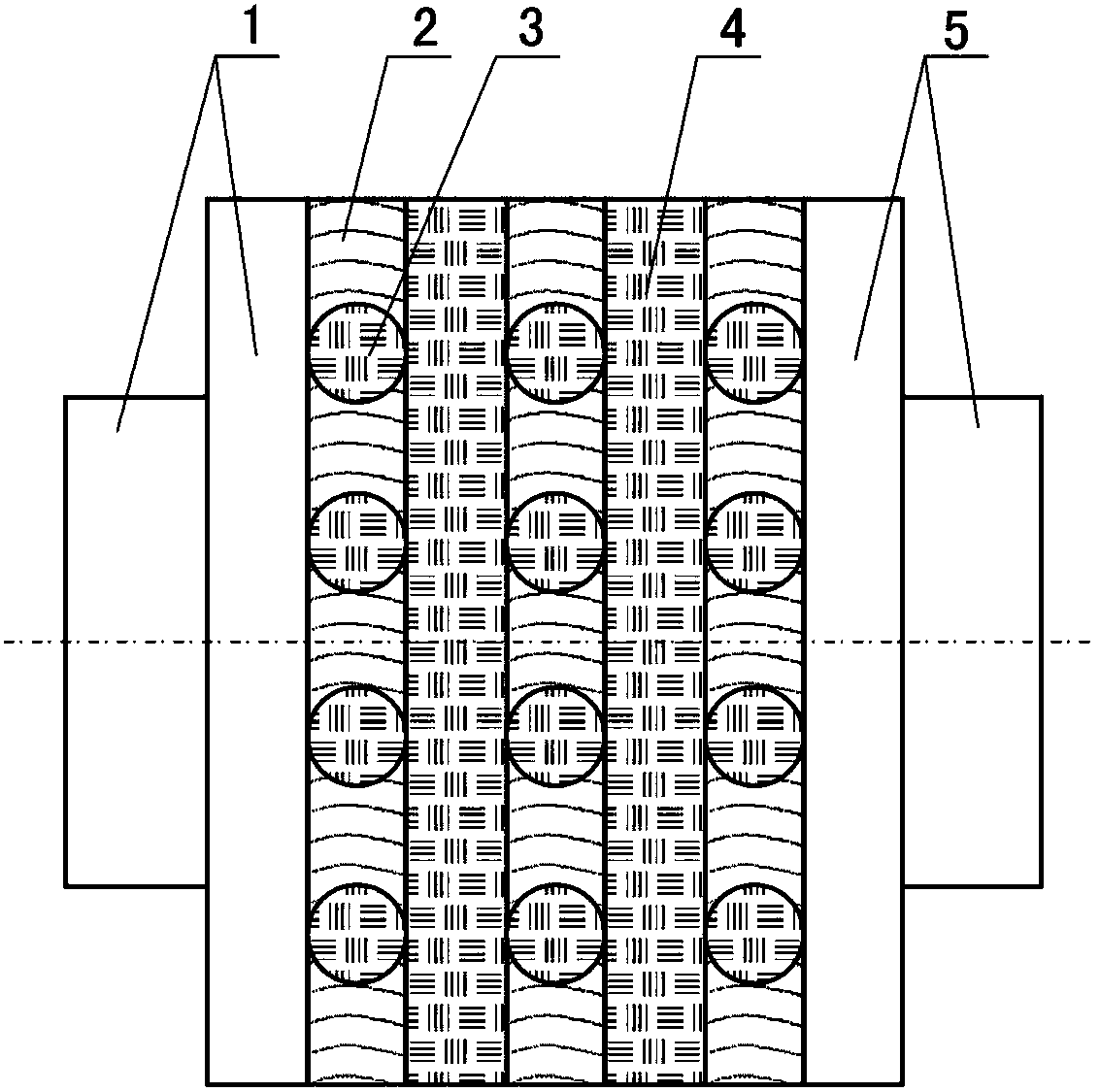
[0026] Such as figure 1 As shown, the gapless force transmission coupling device includes three rubber layers 2 and two steel plates 4, the balls 3 in each rubber layer 2 are evenly distributed in four layers in the direction perpendicular to the force transmission direction, and other structures are the same as those mentioned above. The related structure is the same.

Embodiment 2

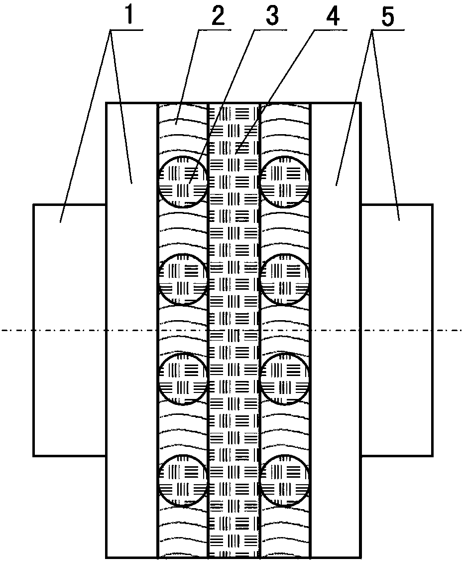
[0028] Such as figure 2 As shown, the non-gap force transmission coupling device includes two rubber layers 2 and a steel plate 4, and other structures are the same as those in Embodiment 1.

Embodiment 3

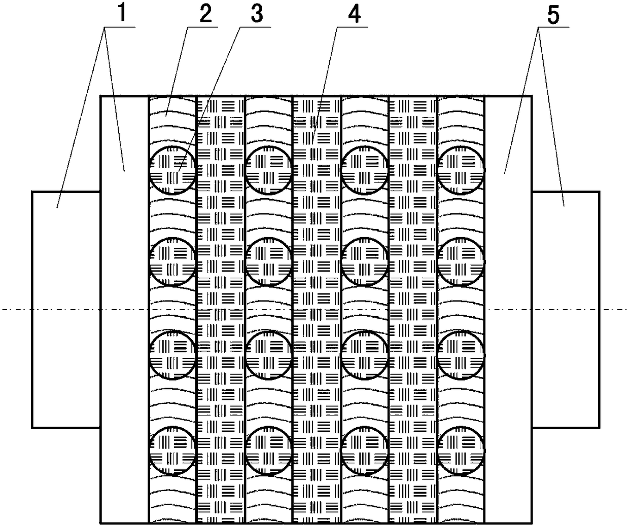
[0030] Such as image 3 As shown, the gapless force transmission coupling device includes four rubber layers 2 and three steel plates 4 in total, and other structures are the same as those in Embodiment 1.

[0031] The quantity of the rubber layer 2 and the steel plate 4 is determined according to the distance between the piston rod of the hydraulic cylinder and the vibration table, the thickness of the rubber layer 2 and the thickness of the steel plate 4 .

[0032] combine Figure 1-Figure 4 , the working principle of the gapless force transmission coupling device that can produce shear deformation in the supergravity field of the present invention is as follows:

[0033] 1. Axial gapless force transmission:

[0034] Such as figure 1 As shown, the axial transmission path of the thrust output by the piston rod of the hydraulic cylinder is: the first connecting flange 1, the first row of balls 3, the first steel plate 4, the second row of balls 3, and the second steel plate...


PUM


Abstract

The invention discloses a no-clearance force transmission coupling device capable of generating shearing deformation in a hyper-gravity field. The no-clearance force transmission coupling device comprises a first connection flange, a second connection flange, steel plates and rubber layers, wherein the first connection flange is used for being connected with a piston rod of a hydraulic cylinder; the second connection flange is used for being connected with a vibration tabletop; one or more of the steel plates and one or more of the rubber layers are separately and alternately arranged between the first connection flange and the second connection flange. The no-clearance force transmission coupling device is characterized by further comprising balls; the plurality of balls are arranged in the rubber layers respectively; two relative tops of all the balls in a force transmission direction are in contact with the steel plates, the first connection flange or the second connection flange respectively. By additionally arranging the balls capable of realizing rigid force transmission and moving along with deformation on the basis of a traditional shearing rubber coupling structure, no-clearance and distortion-free force transmission capable of generating the shearing deformation in the hyper-gravity field can be realized.

Description

technical field [0001] The invention relates to a force transmission coupling device, in particular to a gapless force transmission coupling device capable of shearing deformation in a supergravity field. Background technique [0002] Based on the supergravity field environment provided by the centrifuge, the shaking table model test can generate the same self-weight stress as the prototype, truly reflect the dynamic response of the prototype under natural conditions, and reproduce the deformation and failure mechanism of the geotechnical structure under the action of an earthquake. Therefore, the centrifuge shaking table has become an important simulation test platform for solving related scientific problems in the fields of geotechnical engineering, environmental engineering and hydraulic engineering. [0003] At present, the vibrating table in the hypergravity field is generally driven by hydraulic pressure. As a power actuator, the hydraulic cylinder completes the force...

Claims


Application Information

Patent Timeline
Patent Type & Authority Patents(China)
IPC IPC(8): F16D7/00
CPCF16D7/00
Inventor 李心耀黎启胜洪建忠李明海
Owner GENERAL ENG RES INST CHINA ACAD OF ENG PHYSICS
Why Eureka
Try Eureka