A structure of a shield starting portal and a construction method for shield starting

A construction method and the technology of the starting hole, which is applied in the direction of earthwork drilling, wellbore lining, tunnel lining, etc., can solve the problems of inability to retain soil and water, difficult cutting of shield machine, and large loss of cutter head, etc., and achieve Reduce the scope of reinforcement, achieve sustainable development, and reduce the effect of construction expenditure

Active Publication Date: 2018-02-06
JINAN RAILWAY TRANSPORT GRP CO LTD
View PDF5 Cites 0 Cited by
  • Summary
  • Abstract
  • Description
  • Claims
  • Application Information

AI Technical Summary

Problems solved by technology

The above construction methods all need to take measures to ensure that the water and soil pressure dug inside the tunnel door is in a balanced state, which is prone to the following disadvantages: low safety, the tunnel door should be chiseled before the start of the shield machine, if the shield machine top cannot be removed as soon as possible On the excavation surface, water and sand gushing accidents are likely to occur; the process is complicated, and the door sealing material needs to be chiseled out before the shield tunnel starts, and the steel bars in the maintenance pile should be cleaned and maintained; the construction cost will increase, and if the strength of the hole sealing door material is low, it will not work. On the contrary, if the reinforcement material is too hard and the steel bars of the portal are not cleaned, it will make it difficult for the shield machine to cut and the loss of the cutter head will be huge.

Method used


Image

  • A structure of a shield starting portal and a construction method for shield starting
  • A structure of a shield starting portal and a construction method for shield starting
  • A structure of a shield starting portal and a construction method for shield starting

Examples


Embodiment Construction

[0033] The present invention will be further described below in conjunction with the accompanying drawings and embodiments.

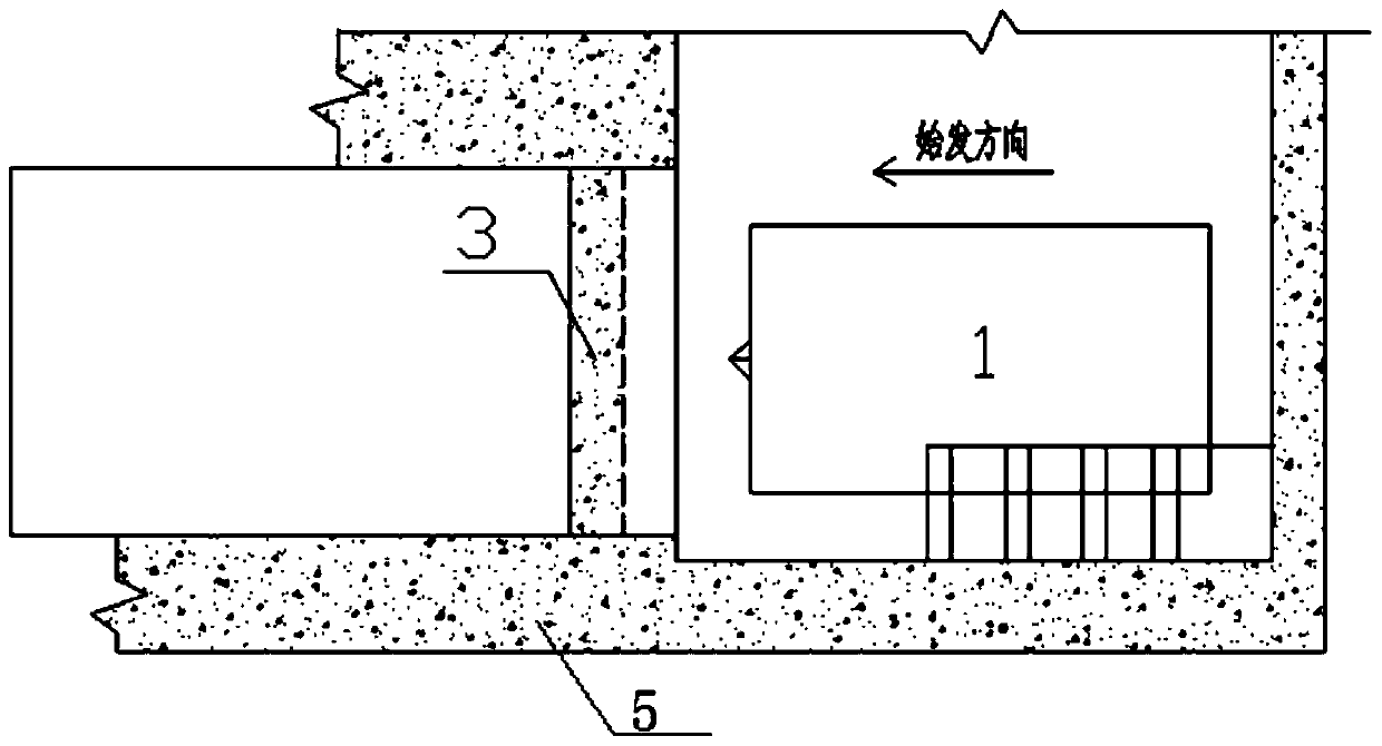
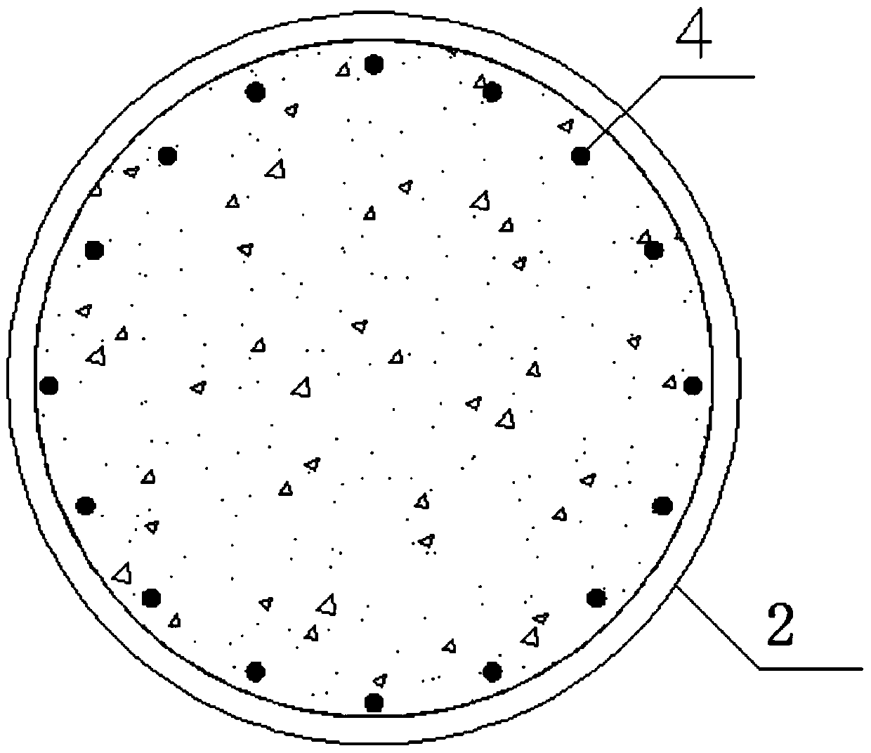
[0034] Such as figure 1 As shown in Fig. 1, the structure of the shield starting portal is mainly composed of arched plain concrete walls, and glass fiber reinforcement is used as an auxiliary reinforcement mode. It mainly includes the main structure 5 of the shield tunnel and the enclosure structure 3. The main structure 5 of the shield tunnel is made of plain concrete walls, and the shield tunnel is formed between the main structures 5 of the shield tunnel. The enclosure structure 3 is formed; the horizontal section of the enclosure structure 3 is arched, and the water and soil pressure outside the shield well is evenly distributed to the rock and soil strata outside the shield well; the enclosure structure 3 is evenly arranged with multiple glass Fiber reinforcement enclosure pile 2.

[0035] The main structure 1 of the shield well is arranged in a...


PUM


Abstract

The invention discloses a structure of a shield launching portal and a shield launching construction method. The structure of the shield launching portal comprises shield shaft main structures. The shield shaft main structures are made of plain concrete walls. A shield tunnel is arranged between the shield shaft main structures. A building enclosure made of a plain concrete wall is arranged at the end of the shield tunnel. The horizontal section of the building enclosure is arched, and the building enclosure can automatically distribute water and soil pressure outside a shield shaft into a rock-soil stratum outside the shield shaft evenly. A plurality of glass fiber rib guard posts are evenly arranged in the building enclosure. The arched plain concrete wall can distribute the water and soil pressure from the outside of the shaft into the rock-soil stratum outside the working shaft evenly, so that the probability that the stress on the upper portion and the lower portion of a conventional sealing portal is nonuniform is lowered, and the self-stabilization capacity of the stratum is brought into full play; through the high tensile strength of glass fiber ribs, deformation of the portal and the stratum around the portal is effectively reduced; and under the existence of the sealing portal, a shield tunneling machine advances directly to cut plain concrete and the glass fiber ribs, and thus the risk of water gushing and sand gushing which are caused by dismounting of the sealing portal is avoided.

Description

technical field [0001] The invention relates to a building structure and a construction method, in particular to a structure of a shield tunnel starting portal and a shield tunnel starting construction method. Background technique [0002] The shield method is a construction method for digging tunnels in the soil layer or soft rock layer below the surface. Shield initiation technology plays a vital role in the entire construction process. The initiation construction operation is the most accident-prone process, which is directly related to the smooth penetration of the shield tunnel. [0003] Conventional shield departure and arrival technology refers to the treatment of the end of the portal before the shield tunneling, the reinforcement of weak ground, the removal of the portal, the design and processing of the shield departure and receiving base, positioning and installation, and the support system , The installation of the door ring, the assembly and disassembly of the ...

Claims


Application Information

Patent Timeline
Patent Type & Authority Patents(China)
IPC IPC(8): E21D9/06E21D11/10E21D11/00E21D9/14
CPCE21D9/06E21D9/14E21D11/00E21D11/10
Inventor 王国富王建路林海
Owner JINAN RAILWAY TRANSPORT GRP CO LTD
Why Eureka
Try Eureka