Eureka AIR delivers breakthrough ideas for toughest innovation challenges, trusted by R&D personnel around the world.

Wastewater treatment device based on carbon nanotube/zinc oxide PTFE photocatalytic membrane and application thereof

A carbon nanotube, photocatalytic membrane technology, applied in energy wastewater treatment, water/sewage treatment, special compound water treatment, etc., can solve the problems of photocorrosion, limit the application of ZnO, etc. The effect of market prospects

Inactive Publication Date: 2016-07-06
HOHAI UNIV
View PDF3 Cites 6 Cited by
  • Summary
  • Abstract
  • Description
  • Claims
  • Application Information

AI Technical Summary

Problems solved by technology

However, during the use of nano-ZnO, serious photocorrosion will occur, which limits the application of ZnO.

Method used


Image

  • Wastewater treatment device based on carbon nanotube/zinc oxide PTFE photocatalytic membrane and application thereof

Examples


Embodiment 1

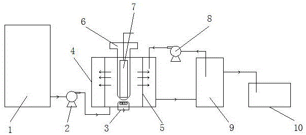
[0026] Wastewater treatment devices based on carbon nanotubes / zinc oxide PTFE photocatalytic membranes, such as figure 1 As shown, it includes a water inlet system, a photocatalytic system, a distillation system, a circulating water system and a water collection system connected in sequence by pipelines. The photocatalytic system includes a quartz cold trap 6 and a light source 7, and the light source 7 is placed in the quartz cold trap 6; the distillation system includes a heater 3, a membrane still 4, a carbon nanotube / zinc oxide PTFE photocatalytic film 5, and the carbon nanotube / zinc oxide PTFE photocatalytic film 5 is made into the shape of a cylinder side, and the photocatalytic system located on the central axis. The water intake system includes a wastewater tank 1 and a water intake pump 2 , the circulating water system includes a circulating water pump 8 and a circulating pool 9 ; the water collection system includes a sump 10 .

[0027] In this embodiment, the pheno...

Embodiment 2

[0029]In this example, dimethyl disulfide wastewater with a concentration of 40 mg / L is used as the target pollutant, and an ultraviolet lamp with a wavelength of 254 nm is used as the light source. The temperature of the hot side of the membrane still-3 is set to 60 ° C, and the temperature of the cold side is room temperature. , the hydraulic retention time is set to 3h, turn on the water inlet pump-2 with a liquid level controller, and the circulating water pump-8 to circulate the hot and cold side water of the membrane distiller, take a sample every 0.5h, and measure the sump-10 The concentration of dimethyl disulfide and COD value in the medium, found that the removal rate of dimethyl disulfide and COD can reach 95%. After the membrane used up in the experiment is ultrasonically cleaned with distilled water for 5-6 hours, the flux of the membrane can be restored to more than 90%.


PUM


Abstract

The invention relates to a wastewater treatment device based on a carbon nanotube / zinc oxide PTFE photocatalytic membrane and an application thereof. The wastewater treatment device comprises a water-in system, a photocatalysis system, a distillation system, a circulating water system and a water collection system, wherein the photocatalysis system comprises a quartz cold trap and a light source arranged in the quartz cold trap; the distillation system comprises a heater, a membrane distiller and a carbon nanotube / zinc oxide PTFE photocatalytic membrane; and the carbon nanotube / zinc oxide PTFE photocatalytic membrane is made into a shape with a cylindrical side surface, and the photocatalysis system is positioned on a center axis. A carbon nanotube / zinc oxide nano catalyst can degrade organic matters in pesticide wastewater under the effect of photocatalysis; and by adopting the PTFE membrane as a carrier, the pollution of the PTFE membrane can be reduced, and the problem that the nano photocatalytic material is hard to recycle in the treatment process is solved. By adopting the method provided by the invention, the removal rate of COD in the pesticide wastewater can exceed 95%, and high purification of the pesticide wastewater is realized; and the method has remarkably high practicability and broad market prospects.

Description

technical field [0001] The invention belongs to the field of pesticide wastewater treatment, and in particular relates to a wastewater treatment device based on a carbon nanotube / zinc oxide PTFE photocatalytic membrane and an application thereof. Background technique [0002] my country is a big agricultural country, and it is also a big country in the production and use of pesticides. According to statistics, in 2004, there were nearly 2,000 pesticide manufacturers in my country, and the annual pesticide production reached 800,000 tons, ranking second in the world. In the process of pesticide production, a large amount of pesticide wastewater will be produced, mainly including wastewater generated during pesticide synthesis, product washing water, workshop and equipment washing water, etc. The composition of pesticide wastewater is complex, highly toxic, containing toxic substances such as benzene rings, phenol, mercury, etc., and has high COD. If it is directly discharged...

Claims


Application Information

Patent Timeline
Patent Type & Authority Applications(China)
IPC IPC(8): C02F9/10C02F101/30
CPCC02F1/02C02F1/30C02F1/44C02F9/00C02F2101/345C02F2201/007C02F2301/08C02F2305/10Y02W10/37
Inventor 陈琳殷绪华朱亮李玉坤赵苇航王俊汪跃谭相君
Owner HOHAI UNIV
Why Eureka
Eureka Blog
Learn More