Hemispherical magnetic pole electro-permanent magnet lifting jack capable of attracting curved surface workpieces

A curved surface workpiece and hemispherical technology, applied in the field of hemispherical magnetic pole electro-permanent magnetic lifter, can solve the problems of cumbersome operation, time-consuming, unable to hold, etc., and achieve the effect of safe and reliable operation, reduced production cost and long service life

Inactive Publication Date: 2016-07-06
天津市可鑫可信磁力机械有限公司
View PDF7 Cites 0 Cited by
  • Summary
  • Abstract
  • Description
  • Claims
  • Application Information

AI Technical Summary

Problems solved by technology

After the magnetic chuck picks up the steel pipe, it is necessary to start the manipulator to clamp from both sides to prevent the steel pipe from sliding and to play a fixed role. The operation is cumbersome, time-consuming, and requires investment in auxiliary equipment
For magnetic chucks and permanent magnet jacks with V-shaped grooves on the suction surface, the angle and width of the V-shaped grooves will change with the diameter of the sucked steel pipe to ensure that the steel pipe is sucked in a suitable position. The V-groove magnetic chuck and permanent magnetic lifter are suitable for a small diameter range of steel pipes, so users need to be equipped with magnetic chucks of various specifications, which in turn increases the user's production costs
In addition, some workpieces with curved contact surfaces are often encountered in machining, and the existing electro-permanent magnetic lifters or electro-permanent magnetic chucks cannot form an effective contact surface with them, so they cannot be held, and thus the The applicable working conditions of the electro-permanent magnetic chuck or electro-permanent magnetic lifter are limited

Method used


Image

  • Hemispherical magnetic pole electro-permanent magnet lifting jack capable of attracting curved surface workpieces
  • Hemispherical magnetic pole electro-permanent magnet lifting jack capable of attracting curved surface workpieces
  • Hemispherical magnetic pole electro-permanent magnet lifting jack capable of attracting curved surface workpieces

Examples


Embodiment Construction

[0015] In order to further understand the invention content, characteristics and effects of the present invention, the following examples are given, and detailed descriptions are as follows in conjunction with the accompanying drawings:

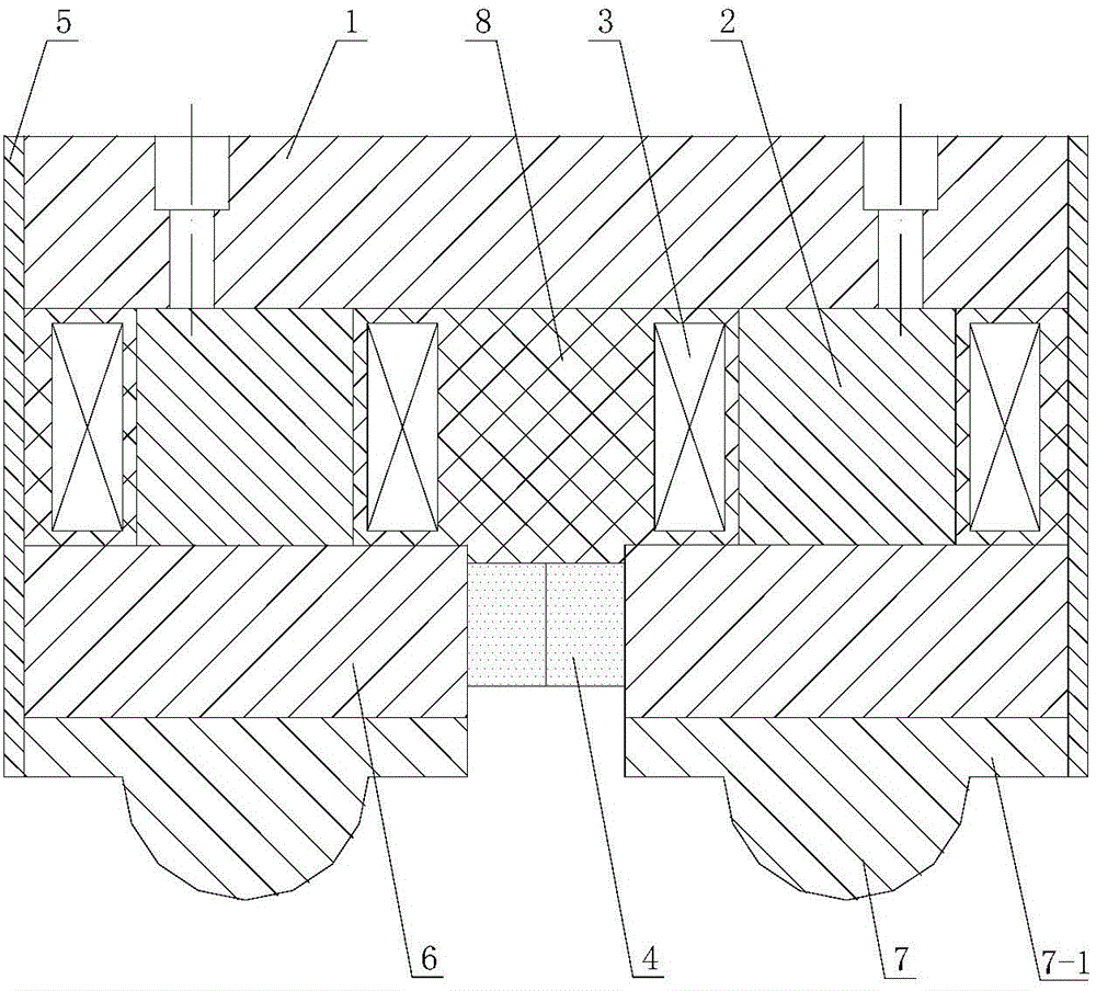
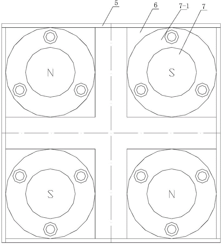
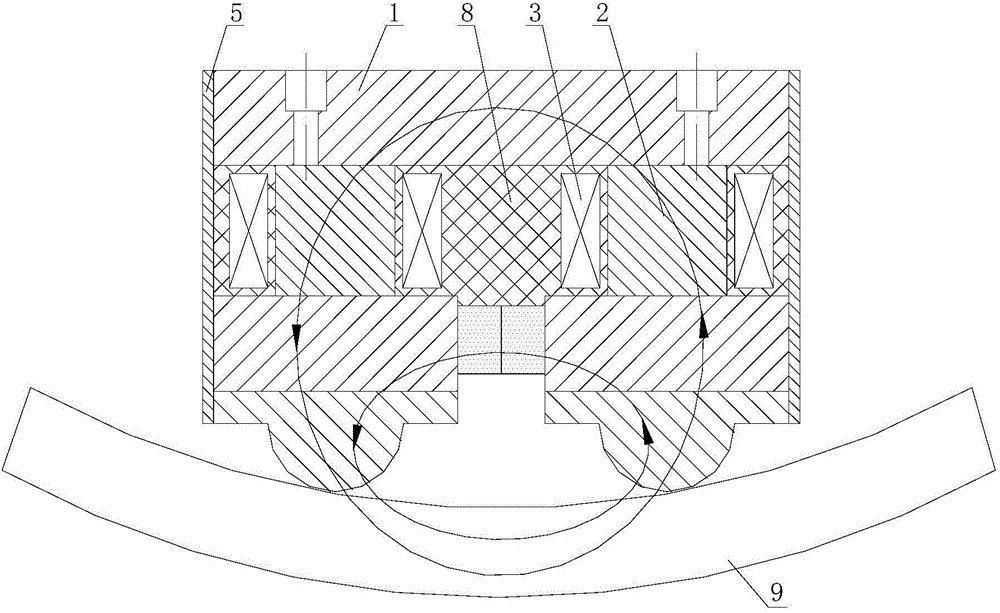
[0016] see figure 1 with figure 2 , a hemispherical magnetic pole electric permanent magnet lifter that can attract curved workpieces, including a base plate 1 made of low-carbon steel, on which a reversible magnet 2 is installed, and a coil 3 is set on the outer ring of the reversible magnet. The top of the reversible magnet is equipped with a plurality of armatures 6, and the main magnet 4 is embedded between the armatures. The non-magnetic metal plate 5 is packaged on the outer surface of the bottom plate and the armature, and resin 8 is poured between the reversible magnet, the coil and the main magnet. . The top of each armature 6 is fixed with a hemispherical magnetic pole 7 that can meet the needs of different curvature surfaces.

...


PUM


Abstract

The invention relates to a hemispherical magnetic pole electro-permanent magnet lifter capable of attracting curved surface workpieces, comprising a bottom plate made of low-carbon steel, on which a reversible magnet is installed, the outer ring of the reversible magnet is fitted with a coil, and the top of the reversible magnet is There are multiple armatures, the main magnet is embedded between the armatures, the non-magnetic metal plate is packaged on the side of the bottom plate and the armature, resin is poured between the reversible magnet, the coil and the main magnet, and the feature is: the top of each armature Both are fixed with hemispherical magnetic poles that can adapt to the needs of different curvature surfaces. The advantages are: adapting to the needs of workpieces with different curvatures and surfaces, the workpiece can be firmly held without additional auxiliary equipment such as manipulators, and the number of magnetic chucks or permanent magnet lifters with various specifications is reduced, which reduces the production cost of users. It adopts a four-pole adsorption structure with strong suction, which is suitable for absorbing both concave and convex surfaces; safe and reliable operation, energy saving, maintenance-free, long service life, and easy to form mass production.

Description

technical field [0001] The invention belongs to the field of clamping tools for mechanical processing, in particular to a hemispherical magnetic pole electro-permanent magnetic lifter capable of attracting curved surface workpieces. Background technique [0002] At present, the suction surface of the electro-permanent magnetic chuck and the permanent magnetic lifter adopts a flat or V-shaped groove structure. For magnetic chucks with a flat suction surface, since the suction surface of the magnetic chuck forms line contact with the steel pipe or spring during the holding process, in order to prevent objects such as steel pipes from rolling and falling, a set of mechanical engagement devices must be added. After the magnetic chuck picks up the steel pipe, it is necessary to start the manipulator to clamp from both sides to prevent the steel pipe from sliding and to play a fixed role. The operation is cumbersome, time-consuming, and requires investment in auxiliary equipment. ...

Claims


Application Information

Patent Timeline
IPC IPC(8): B66C1/06
Inventor 李敬品徐式逴
Owner 天津市可鑫可信磁力机械有限公司
Why Eureka
Try Eureka