Modular wire-driven continuum robotic arm
A modular and continuum technology, applied in the field of robotic arms, can solve the problems of inability to realize continuous deformation and insufficient flexibility, and achieve the effects of easy promotion, flexible movement and reasonable layout
- Summary
- Abstract
- Description
- Claims
- Application Information
AI Technical Summary
Problems solved by technology
Method used
Image

Examples
Embodiment 1
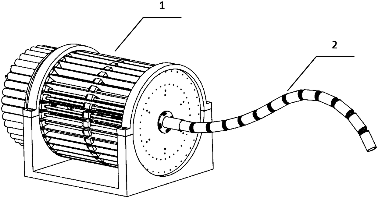
[0041] In this example, if figure 1 Shown is a schematic diagram of the overall structure of the wire-rope-driven continuum robot provided by the present invention. It is mainly composed of a continuum robot driving device 1 and a continuum robot manipulator 2 . Wherein 1 is a continuum robot driving device, and the design content has been introduced in detail in the publication number CN105058423A. figure 2 There is a rope-driven continuum robotic arm with motion decoupling, which has been introduced in detail in the patent publication CN105014689A. The continuum robot drive device introduced in the publication number CN105058423A has certain versatility for the mechanical arm driven by the wire, for example, it can drive the mechanical arm introduced in the patent CN105014689A. This type of wire-driven mechanical arm can have a variety of design schemes, and its structural features and advantages are different.
[0042] The modular cord-driven continuum mechanical arm pr...
Embodiment 2
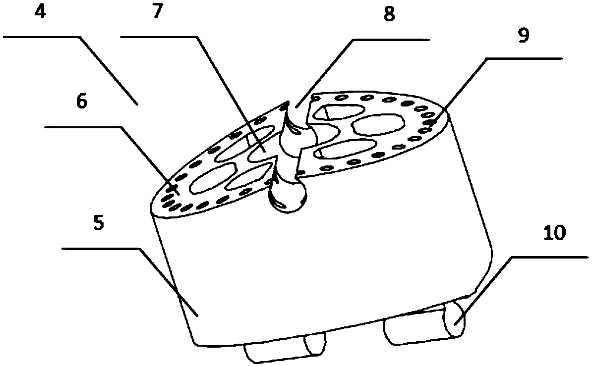
[0055] The second embodiment is a modified example of the first embodiment. The main difference between the second embodiment and the first embodiment is that in the second embodiment, the upper end surface of the modular unit is provided with an upper ball joint surface 18 and the upper arc sweeping surface, the lower end surface is provided with a lower spherical hinge surface 15 and a lower arc sweeping surface 14;
[0056] A hinge structure is formed between the upper ball joint surface 18 of one modular unit and the lower ball joint surface 15 of another modular unit, specifically a ball joint structure.
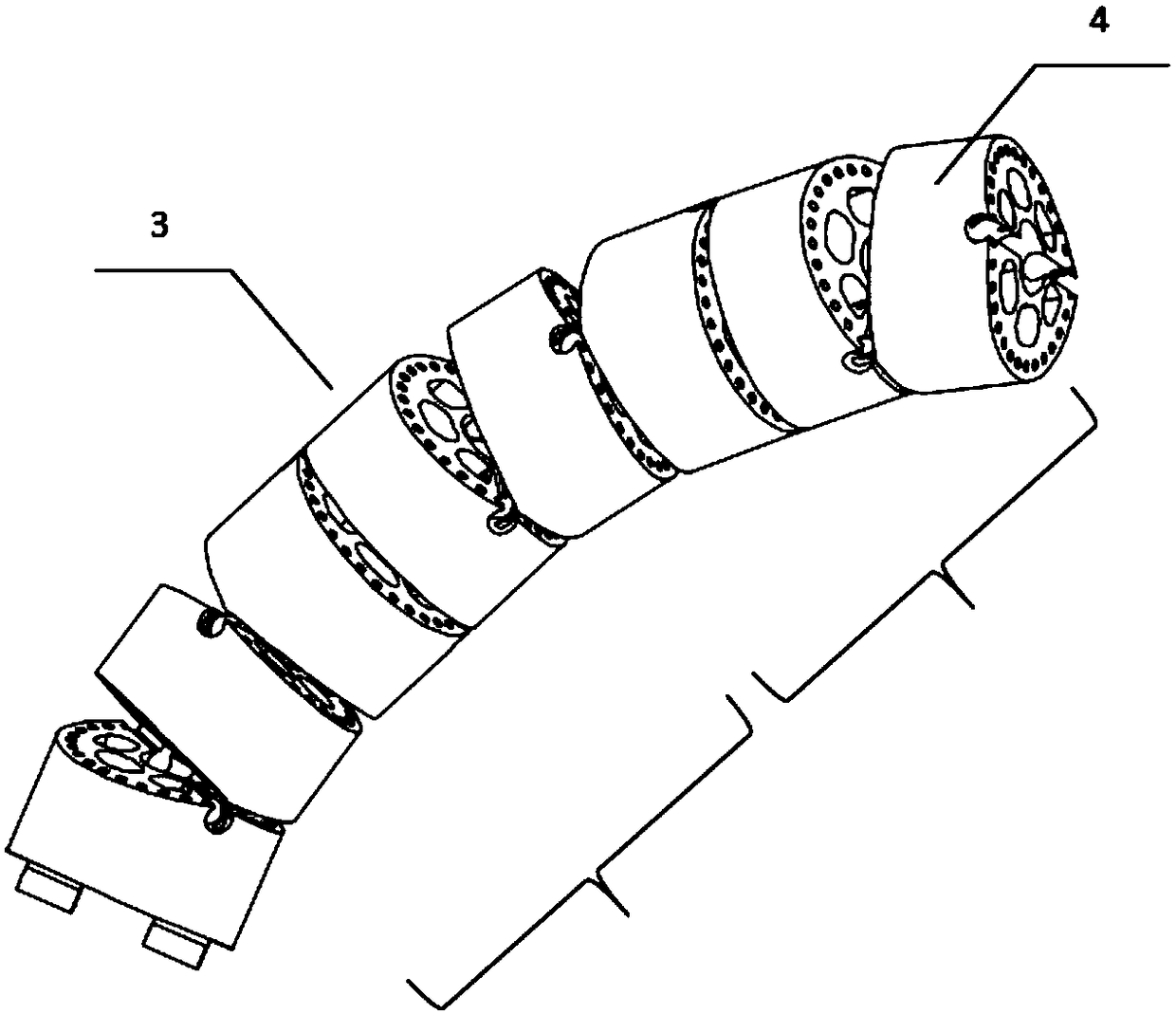
[0057] Such as Figure 4 As shown, in Embodiment 1, when the symmetrical centerlines of the upper and lower end surfaces are not parallel, the manipulator section 3 can rotate in multiple directions, but the rotation directions are discrete and limited, and cannot rotate in any direction. The second type of modular cord-driven continuum manipulator is obtained by sweep...
Embodiment 3
[0060] The third embodiment is a modification of the first embodiment. The main difference between the third embodiment and the first embodiment is that in the third embodiment, the upper end surface of the modular unit is provided with The blind hole channel 23, the lower end surface is provided with a flexible rod 26 matching the blind hole channel 23;
[0061] The end of the flexible rod 26 is provided with a fixed hinge 25; the bottom of the blind hole channel 23 is provided with a spherical groove matching the fixed hinge 25;
[0062] The flexible rod 26 of one modular unit forms a hinge structure through the fixed hinge 25 and the blind hole channel 23 of the other modular unit.
[0063] Such as Image 6 As shown, in Embodiment 1 and Embodiment 2, since the modular units themselves are relatively large, and the range of motion between the modular units is relatively large, about 4 modular units can be selected according to the requirements of the range of motion and fle...
PUM
 Abstract
Description
Claims
Application Information
 - R&D
- Intellectual Property
- Life Sciences
- Materials
- Tech Scout
- Unparalleled Data Quality
- Higher Quality Content
- 60% Fewer Hallucinations
Browse by: Latest US Patents, China's latest patents, Technical Efficacy Thesaurus, Application Domain, Technology Topic, Popular Technical Reports.
© 2025 PatSnap. All rights reserved.Legal|Privacy policy|Modern Slavery Act Transparency Statement|Sitemap|About US| Contact US: help@patsnap.com