Tool storage rack
A technology for placing racks and knives, applied in tool storage devices, manufacturing tools, etc., can solve the problems of multiple handling, limited number of knives placed, inconvenient tool replacement, etc.
- Summary
- Abstract
- Description
- Claims
- Application Information
AI Technical Summary
Problems solved by technology
Method used
Image
Examples
Embodiment 1
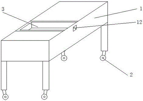
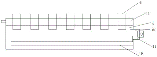
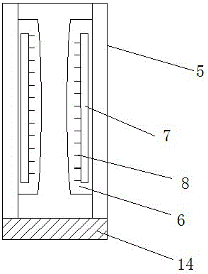
[0024] Such as figure 1 , figure 2 with image 3 As shown, a tool placement rack includes a frame 1, a pulley 2 is provided at the bottom of the frame 1, a placement groove 3 is provided on the frame 1, a tool placement box 4 is arranged in the placement groove 3, and the tool placement box 4 There is an accommodation cavity 5 in the interior, and a sponge pad 6 is attached to the accommodation cavity 5. An oil bag 7 is arranged in the sponge pad 6, and the oil bag 7 is filled with antirust oil. The surface layer of the oil bag 7 is attached with some antirust thin tube of oil8.
[0025] An electromagnet 9 is arranged below the accommodating cavity 5 , and the electromagnet 9 is connected to an external power source through the connection between the tool placement box 4 and the placement slot 3 .
Embodiment 2
[0027] To further improve the above structure, the structure is as follows:
[0028] Such as figure 1 , figure 2 with image 3 Shown, a kind of cutter placement frame comprises frame 1, and the bottom of frame 1 is provided with pulley 2, and frame 1 is provided with several placement grooves 3, and placement groove 3 is provided with cutter placement box 4, and described placement box 4 The outside is provided with an adapter 10 docked with the placement slot 3, and the adapter 10 is provided with a conduction device 11 for external power supply. The placement slot 3 is provided with a socket for receiving the adapter 10, and the placement slot 3 outside A socket 12 for connecting the power supply is provided, and a switch is provided on the socket 12; the cutter placement box 4 includes a cutter board 12 and a box body, and the cutter board 13 is covered on the box body by a slot, and the cutter board 13 is provided with A number of accommodation cavities 5, a sponge pad...
Embodiment 3
[0031] To further improve the above structure, the structure is as follows:
[0032] Such as figure 1 , figure 2 with image 3 Shown, a kind of cutter placement frame comprises frame 1, and the bottom of frame 1 is provided with pulley 2, and frame 1 is provided with several placement grooves 3, and placement groove 3 is provided with cutter placement box 4, and described placement box 4 The outside is provided with an adapter 10 docked with the placement slot 3, and the adapter 10 is provided with a conduction device 11 for external power supply. The placement slot 3 is provided with a socket for receiving the adapter 10, and the placement slot 3 outside A socket 12 for connecting the power supply is provided, and a switch is provided on the socket 12; the cutter placement box 4 includes a cutter board 12 and a box body, and the cutter board 13 is covered on the box body by a slot, and the cutter board 13 is provided with A number of accommodation cavities 5, a sponge pad...
PUM
 Abstract
Description
Claims
Application Information
 - R&D Engineer
- R&D Manager
- IP Professional
- Industry Leading Data Capabilities
- Powerful AI technology
- Patent DNA Extraction
Browse by: Latest US Patents, China's latest patents, Technical Efficacy Thesaurus, Application Domain, Technology Topic, Popular Technical Reports.
© 2024 PatSnap. All rights reserved.Legal|Privacy policy|Modern Slavery Act Transparency Statement|Sitemap|About US| Contact US: help@patsnap.com


