Knife sharpener

A knife sharpener and linkage rod technology, used in grinding/polishing equipment, grinding/polishing hand tools, metal processing equipment, etc., can solve the problem of occupying storage space, difficult to improve production efficiency, and single function of the sharpener question

Pending Publication Date: 2020-08-11
中山市海巍厨具有限公司
View PDF0 Cites 0 Cited by
  • Summary
  • Abstract
  • Description
  • Claims
  • Application Information

AI Technical Summary

Problems solved by technology

The function of the existing knife sharpener is relatively simple, generally only has the function of sharpening the knife, the existing knife sharpener does not have the functions of hanging plate, hook, suction cup, etc., and cannot meet the various needs of users, and the existing sharpener All knives need to take up storage space, which is inconvenient to store
In addition, the sharpening specifications of existing knife sharpeners are relatively single. Usually, a knife sharpener is only equipped with a sharpening structure of one specification, and can only perform grinding operations of a single mesh. When users need different sharpening requirements, , only different types of sharpeners can be purchased at the same time, which greatly increases the purchase cost of users. At the same time, too many sharpeners are not convenient for users to carry and use
In addition, the existing sharpening edge is generally provided with two sharpening bars, and the two sharpening bars are cross-displaced to form angled grooves. In this way, the number of parts is large, the assembly process is cumbersome and complicated, and the production efficiency is difficult to improve. Once one of the sharpening bars is displaced, it will affect the sharpening effect and affect the service life of the sharpener

Method used


Image

  • Knife sharpener
  • Knife sharpener
  • Knife sharpener

Examples


Embodiment Construction

[0018] It should be understood that the specific embodiments described here are only used to explain the present invention, not to limit the present invention.

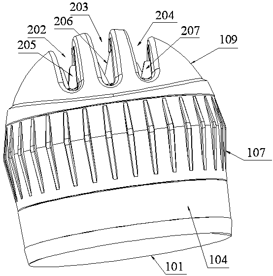
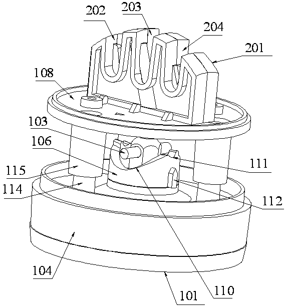
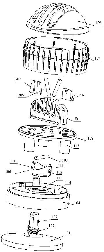
[0019] refer to Figure 1 to Figure 5 , an embodiment of a knife sharpener of the present invention is proposed, which includes a vacuum suction cup with a linkage rod 102 that can be adsorbed on a plane, fixed on the linkage rod 102 and can drive the linkage rod 102 to move longitudinally The linkage pin 103, the base 104 sleeved outside the linkage rod 102 and positioned above the vacuum chuck, and the base 104 sleeved outside the linkage rod 102 and clamped between the base 104 and the vacuum chuck play a reset role on the vacuum chuck The return spring 105, the rotating seat 106 that is arranged on the base 104 and is sleeved outside the linkage rod 102 and can drive the linkage pin 103 to move longitudinally, the turntable 107 that is installed on the top of the base 104 and is linked with the rotating seat 106, ...


PUM


Abstract

The invention discloses a knife sharpener. The knife sharpener comprises a vacuum sucker capable of being adsorbed on a plane and provided with a linkage rod, a linkage pin fixedly arranged on the linkage rod and capable of driving the linkage rod to longitudinally move, a base arranged outside the linkage rod in a sleeving manner and located above the vacuum sucker, a reset spring arranged outside the linkage rod in a sleeving manner and clamped between the base and the vacuum sucker to reset the vacuum sucker, a rotary seat arranged on the base, arranged outside the linkage rod in a sleevingmanner and capable of driving the linkage pin to longitudinally move, a rotary disc mounted above the base and linked with the rotary seat, a knife sharpening bottom plate located above the rotary disc and connected and fixed to the base, a knife sharpening structure fixedly arranged on the knife sharpening bottom plate, and a knife sharpening cover arranged on the knife sharpening bottom plate in a covering manner. The vacuum sucker comprises a sucker in a hollow cone shape, and the linkage rod arranged at the upper end of the sucker. The rotary seat rotates along with rotation of the rotarydisc, an arc-shaped bevel edge capable of driving the linkage pin to move is arranged at the upper end of the rotary seat, and an arc-shaped positioning groove clamped with the linkage pin is formedin the highest position of the arc-shaped bevel edge.

Description

technical field [0001] The invention relates to the technical field of knife sharpeners, in particular to a knife sharpener. Background technique [0002] Compared with traditional knife sharpeners, modern knife sharpeners have the advantages of fast sharpening speed, simple operation, convenient portability, and beautiful appearance. It is a scientific, practical, efficient and convenient sharpening tool, suitable for kitchen knives Outdoor knives, Damascus knives, ceramic knives and other knives are characterized by changing the traditional single-sided sharpening to double-sided sharpening, so that the method, angle, and efficiency of sharpening have undergone fundamental changes, and the sharpening efficiency has improved. Greatly improved, modern knife sharpeners are more and more widely used in daily life. The function of the existing knife sharpener is relatively simple, generally only has the function of sharpening the knife, the existing knife sharpener does not ha...

Claims


Application Information

Patent Timeline
IPC IPC(8): B24D15/02B24D15/08
CPCB24D15/02B24D15/08
Inventor 朱国栋
Owner 中山市海巍厨具有限公司
Why Eureka
Try Eureka