
Novel partial fourteen-roller steel plate cold rolling mill structure

A technology of cold rolling mill and steel plate, applied in the direction of metal rolling stand, metal rolling mill stand, metal rolling, etc., can solve the problem of unreasonable force distribution, unreasonable layout of force system, and inability to control and adjust the rolling board and other issues

Active Publication Date: 2016-07-06
CHINA NAT HEAVY MACHINERY RES INSTCO
View PDF7 Cites 5 Cited by
  • Summary
  • Abstract
  • Description
  • Claims
  • Application Information

AI Technical Summary

Problems solved by technology

Although the depressing device system is relatively simple, the arrangement of the force system in this device is seriously unreasonable
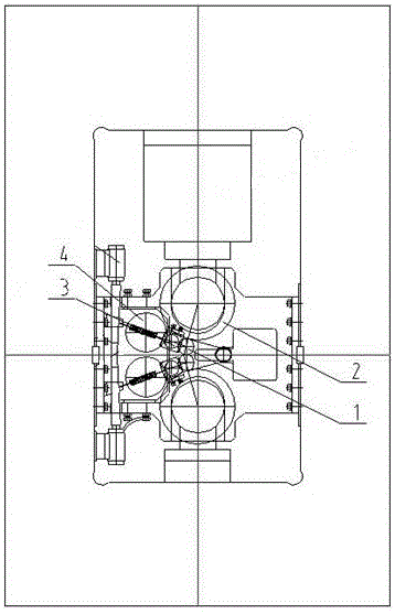
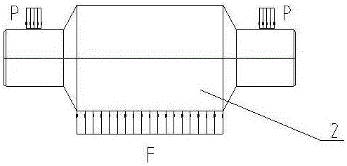
The rolling force P generated by the oil cylinder acts on both ends of the back-up roll, while the resistance force F generated by the rolled steel plate acts on the middle of the back-up roll, and a bending moment is generated on the back-up roll, causing the back-up roll to bend Therefore, compensation measures such as bending rolls, drawing rolls, and roll surface pre-grinding crowns are used, but none of them can control and adjust the defects at any point on the surface of the rolled plate. Therefore, traditional rolling mills continue to use this type of rolling system. The force distribution is very unreasonable, which greatly hinders the improvement of the quality of rolled products
[0005] Due to the above two main shortcomings of the partial eight-high steel plate cold rolling mill, the development of this type of rolling mill is greatly restricted

Method used


Image

  • Novel partial fourteen-roller steel plate cold rolling mill structure
  • Novel partial fourteen-roller steel plate cold rolling mill structure
  • Novel partial fourteen-roller steel plate cold rolling mill structure

Examples


Embodiment 1

[0027] as attached figure 1 As shown, the existing eight-high steel plate cold rolling mill is transformed on the basis of the traditional four-high rolling mill. The work roll is deviated from the center line of the roll by a distance, and a transition support roll 3 and a backing bearing roll 4 are added. and support roll 2 to ensure the rigidity of the work roll 1. The steel plate shape adjustment of the partial eight-roll steel plate cold rolling mill relies on the upward pressure of the oil cylinder and the pressure on the top plate through the wedge. The pressure acts on the shaft of the backing bearing and It produces local bending to increase the longitudinal rigidity of the rolling mill when the bending part is rolled, so as to locally increase the deformation of the rolled steel plate and achieve the purpose of adjusting the shape of the plate. But its adjustment effect is not obvious, and the force acting on the backing bearing is very large when the plate shape is ...

Embodiment 2

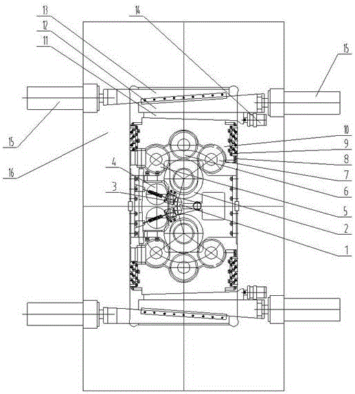
[0033] On the basis of Embodiment 1, the described depressing device includes an upper wedge 13, a lower wedge 12 and an adjustable support block 10 arranged in sequence from far to near, and the tail end of the upper wedge 13 and the lower wedge 12 Oil cylinders 15 are respectively connected, and the oblique wedge angles of the upper wedge 13 and the lower wedge 12 are the same, and the thinner tips of the upper wedge 13 and the lower wedge 12 are arranged in opposite directions. Sliding fit with the opposite surface of the lower wedge 12, the adjustable support block 10 is provided with several, and several adjustable support blocks 10 are evenly arranged under the lower wedge 12, the adjustable support block 10 adopted in the present invention It is an existing product, and will not be described in detail. The contact surface between the adjustable support block 10 described in this embodiment and the backing bearing roll below it is a semicircular arc surface, and the semic...

Embodiment 3

[0036] On the basis of Embodiment 2, several wedges 11 are arranged between the lower wedge 12 and the several adjustable support blocks 10, and several oil cylinders 14 are correspondingly connected to the several wedges 11 respectively. When it is necessary to adjust the plate shape at a certain point, one of the oil cylinders 14 corresponding to the adjustment point enters the pressure oil, and pushes the wedge 11 at the corresponding point of the oil cylinder to move downward, and the wedge 11 bears against the corresponding The adjustable support block 10 at the point is pressed down, and when the adjustable support block 10 moves downward, the shaft and the backing bearing pressing the corresponding point move down, so that the shaft of the backing bearing is slightly bent at this point to increase The longitudinal rigidity of the roller system at this point can complete the adjustment of the plate shape reduction in the transverse direction of the rolled steel plate surf...


PUM


Abstract

The invention provides a novel partial fourteen-roller steel plate cold rolling mill structure. A roller system is arranged in a J form; the structure comprises a set of working rollers, three sets of support rollers, three sets of back lining bearing rollers and a set of pressing devices symmetrically arranged up and down along a roller center line; the working rollers are deviated from the roller center lien by a certain distance, are supported by middle support rollers in the vertical direction, and are supported by transition support rollers and side support rollers in the side direction; the three sets of back lining bearing rollers are arranged on the peripheral surfaces, far from one sides of the working rollers, of the support rollers in sequence; multiple back lining bearings are respectively arranged in axial directions of three back lining bearing rollers; the bearings are arranged in a staggered manner; indentations cannot be generated among the rollers; and the pressing devices are clamped on shafts among bearings of the back lining bearing rollers. The roller system in rolling work is stable in structure, excellent in rigidity and capable of adjusting the convexity of the working rollers at any time to finish the plate shape adjustment; the rolling force and the deformation resistance of rolled steel are both directly acted in a roller surface range of the rollers; and the support rollers are not suffered from the bending moment, and generate no bending deformation, so that the plate rolling precision is higher.

Description

technical field [0001] The invention belongs to the technical field of metallurgy, and relates to a steel plate cold rolling mill, in particular to a structure of a novel partial fourteen-high steel plate cold rolling mill. Background technique [0002] The existing partial eight-high steel plate cold rolling mill, such as figure 1 As shown, it is modified on the basis of the traditional four-high rolling mill. It is to reduce the diameter of the work rolls to meet the requirements of rolling harder and thinner steel plates (strips). Due to the reduction of the diameter of the work roll, the decrease of its stiffness will affect the quality of the rolled product, so it is considered to deviate the work roll from the center line of the roll by a distance, and add a transition support roll, a backing bearing roll and a support roll to ensure the stability of the work roll. stiffness. There are problems: [0003] 1. The adjustment of the steel plate shape depends on the upwa...

Claims


Application Information

Patent Timeline
Patent Type & Authority Applications(China)
IPC IPC(8): B21B13/02B21B31/30
CPCB21B13/02B21B31/30
Inventor 王胜翔王建国
Owner CHINA NAT HEAVY MACHINERY RES INSTCO
Learn More