
Inspection system, inspection method, and readable recording medium

An inspection system and sampling inspection technology, applied in the direction of optical testing flaws/defects, instruments, measuring devices, etc., can solve the problems of discrete differences in the characteristic values ​​of inspection blocks, and achieve the effect of stable grade division and good production quality.

Inactive Publication Date: 2016-06-29
SHARP KK
View PDF12 Cites 2 Cited by
  • Summary
  • Abstract
  • Description
  • Claims
  • Application Information

AI Technical Summary

Problems solved by technology

[0012] When the inspection block dividing unit 107 divides the inspection target region so that the number of components included in the inspection blocks is approximately the same, there is a possibility that the dispersion of the characteristic values ​​in each inspection block may be greatly different.

Method used


Image

  • Inspection system, inspection method, and readable recording medium
  • Inspection system, inspection method, and readable recording medium
  • Inspection system, inspection method, and readable recording medium

Examples


Embodiment approach 1

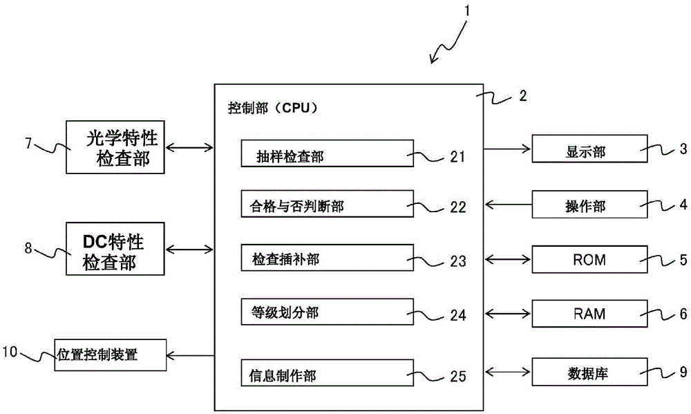
[0086] figure 1 It is a block diagram showing an example of the main part hardware configuration of the inspection system according to Embodiment 1 of the present invention.

[0087] exist figure 1 Among them, the inspection system 1 of the first embodiment is composed of a computer system, including: a CPU2 (central processing unit) as a control unit for overall control; an initial screen, a selected scene, and a control result screen of the CPU2 are displayed on the display screen. and the display unit 3 of the operation input screen, etc.; the keyboard, mouse, and touch panel for inputting instructions to the CPU 2, and the operation unit 4 of an input device such as receiving an input via a communication network (such as the Internet, an intranet); ROM5 of a computer-readable recording medium for programs and its data, etc.; reads the control program and its data, etc. at startup, reads and stores data in each control performed by the CPU2, and operates as a work memory...

Embodiment approach 2

[0180] For the above Embodiment 1 Figure 5 (b) and Figure 5 The flow example in (c) described the case where the sampling inspection of optical characteristics and the entire inspection of DC characteristics are performed using different flows. However, in the second embodiment, as Figure 5 (d) and Figure 5 As in the flow example of (e), a case will be described in which inspection (OPT+DC) is performed by integrating the single-unit measurement of optical characteristics and multiple simultaneous measurement functions of DC characteristics in one device. In addition, in this Embodiment 2, except Figure 5 (d) and Figure 5 Other than the flow example of (e), other content such as (number of interpolation data; number of sampling chips), (example of pre-evaluation of the introduction of the number of sampling chips), (judgment criteria for pre-evaluation of the introduction of the number of sampling chips; interpolation inspection evaluation Judgment criteria), (interp...


PUM


Abstract

The present invention inspects all DC characteristics, inspects the optical characteristics of a sample, is capable of more stable grading, and enhances delivery quality. A CPU (2) is provided as a control unit for controlling the creation of information that has been ranked and divided by a grading unit (24) into information about each grade of light emitting element group on the basis of map information synthesized from: optical element optical characteristic values collected by a sampling inspection unit (21) from sampling inspection carried out by an optical characteristic inspection unit (7) for each of a prescribed number of optical elements, optical characteristic values for uninspected light emitting elements determined through interpolation by an inspection interpolation unit (23) on the basis of the plurality of optical characteristic values from the sampling inspection by the optical characteristic inspection unit (7), and quality information (nondefective product / defective product information) determined by a pass / fail determination unit (22) from the inspection of the electrical characteristics (DC characteristics) of all the plurality of optical elements on the entire surface of a wafer by a DC inspection unit (8).

Description

technical field [0001] The present invention relates to an inspection system for performing various inspections on a plurality of semiconductor chips on a semiconductor wafer, an inspection method using the inspection system, and a control program storing a processing flow for causing a computer to execute each step of the inspection method computer-readable storage medium. Background technique [0002] In a manufacturing process using a semiconductor process, semiconductor chips are formed in a matrix on a wafer. The formed semiconductor chips are inspected for good and bad at the stage of commercialization. For example, there are cases where inspection is performed in the state of a wafer, cases where inspection is performed in a state where individual chips are separated from the wafer, and cases where final inspection is performed after mounting in a package, and the like. In the inspection of this semiconductor chip, even in light-emitting components represented by LE...

Claims


Application Information

Patent Timeline
Patent Type & Authority Applications(China)
IPC IPC(8): G01N21/95
CPCG01N21/9501
Inventor 内田练石川真治斋藤仁尾上毅案野宏隆佐藤刚
Owner SHARP KK
Learn More