
Wind field reconstruction method based on compressive sensing

A compressed sensing and wind field technology, applied in data processing applications, instruments, calculations, etc., can solve the problems of rapid decline in prediction accuracy, slow calculation speed, difficulty in providing wind speed distribution of wind turbines, etc. fast effect

Active Publication Date: 2016-06-29
NORTH CHINA ELECTRIC POWER UNIV (BAODING)
View PDF6 Cites 3 Cited by
  • Summary
  • Abstract
  • Description
  • Claims
  • Application Information

AI Technical Summary

Problems solved by technology

The accuracy of applying statistical methods to predict wind fields depends on a large number of data samples, so the amount of calculation is relatively large, especially when the prior probability distribution of parameters is relatively complex, especially when the parameter dimension is relatively high, the calculation speed of traditional statistical methods will be relatively slow
[0005] The disadvantage of using the physical atmospheric model method to predict the wind field is that researchers need to have a wealth of meteorological knowledge and understand the physical characteristics. If the model is rough, the prediction accuracy will drop rapidly.
However, at such a large scale as the wind field, solving the conservation equations of fluid dynamics (such as the Navier-Stokes equations) and obtaining the wind speed distribution with a higher spatial resolution will require a huge amount of data processing, which will require a huge Computational resources and capabilities. At present, it is difficult for this method to provide detailed wind speed distribution on the scale of wind turbines

Method used


Image

  • Wind field reconstruction method based on compressive sensing
  • Wind field reconstruction method based on compressive sensing
  • Wind field reconstruction method based on compressive sensing

Examples


Embodiment Construction

[0019] The technical scheme of the patent of the present invention will be described in further detail below in conjunction with specific embodiments.

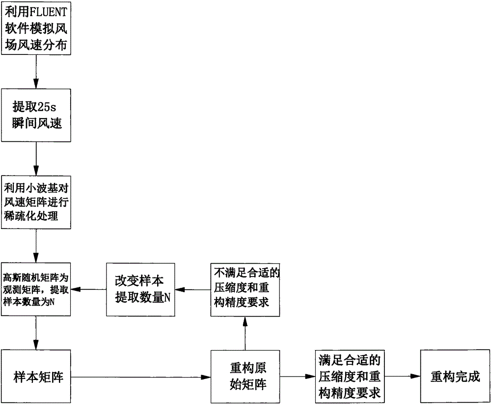
[0020] see figure 1 , a wind field reconstruction method based on compressed sensing, the calculation model of the present invention selects a 100m×100m wind field, and both sides of the wind field are affected by the boundary, which will generate a boundary layer. The x direction is the horizontal direction, and the y direction is the direction in which the wind passes through the wind field.

[0021] Initially, the wind speed is 1m / s and the direction is perpendicular to the entrance and enters the wind field along the y direction. When the inlet wind speed changes, the impact on the field will also be taken into consideration. Assume that after a certain moment, the wind speed between x=-10m and x=10m at the entrance increases to 5m / s, and the direction is still perpendicular to the entrance into the wind field, and then ...


PUM


Abstract

The invention discloses a wind field reconstruction method based on compressive sensing.A calculation model is a wind field, the two sides of the wind field are affected by the boundary, and a boundary layer will be generated.The X direction is a horizontal direction, the y direction is the direction where wind passes the wind field, the wind speed direction is perpendicular to an inlet, wind enters the wind field in the y direction, after the inlet wind speed changes, influences on the field are calculated, speed fields generated before and after the inlet wind speed changes are compared, a field with peak value areas will be obtained at a certain moment when disturbance is pushed forwards, most points of the field are in the net added-value state, a computational area performs computation through theories such as the Bell operation, a mass conservation equation, a momentum conservation equation and a turbulent kinetic energy and turbulent kinetic energy dissipation rate equation, and sparse treatment is performed on a matrix by means of a proper wavelet basis.The method can be used for fast predicting the wind field, and data on lots of grids are reconstructed through little calculation.Operation time is shorter compared with that of a traditional prediction method.

Description

technical field [0001] The invention relates to the field of wind field prediction, in particular to a wind field reconstruction method based on compressed sensing. Background technique [0002] Wind energy is an inexhaustible clean energy with huge reserves. Referring to statistics from the World Wind Energy Association, the total installed capacity of wind power in the world reached 120.791 million kw in 2008, with an annual growth rate of 28.7%, even higher than the average growth rate in the past ten years. Wind power generation has been widely used all over the world. By the end of 2008, more than 70 countries around the world had built wind farms. There is widespread acceptance of wind power generation as an alternative energy technology worldwide. [0003] The purpose of short-term wind field forecasting is to directly or briefly predict the output of wind farms (the wind field is first estimated and then converted into electricity). Short-term forecasting is mainl...

Claims


Application Information

Patent Timeline
IPC IPC(8): G06F17/50G06Q50/06
CPCG06Q50/06G06F30/00
Inventor 孙莹孙单勋张景胤刘石
Owner NORTH CHINA ELECTRIC POWER UNIV (BAODING)
Learn More