
Dual Power Electromagnetic Brake

A technology of electromagnetic brakes and brakes, which is applied in the direction of brake actuators, gear transmission mechanisms, mechanical equipment, etc., can solve the problems of affecting the working life of electromagnetic brakes, rising coil temperature, and burning out coils, so as to reduce thermal effects and improve work efficiency. The effect of longevity and convenient control

Inactive Publication Date: 2018-09-21
CHONGQING HUAYU ELECTRIC GRP
View PDF7 Cites 0 Cited by
  • Summary
  • Abstract
  • Description
  • Claims
  • Application Information

AI Technical Summary

Problems solved by technology

At present, the electromagnetic brakes on the market use high currents to pull in and hold, and high currents will increase the temperature of the coils. If the time is too long, the coils will burn out. If the current is too high, the power will be wasted and the working life of the electromagnetic brakes will be affected.

Method used


Image

  • Dual Power Electromagnetic Brake
  • Dual Power Electromagnetic Brake
  • Dual Power Electromagnetic Brake

Examples


Embodiment Construction

[0032] The following will clearly and completely describe the technical solutions in the embodiments of the present invention with reference to the accompanying drawings in the embodiments of the present invention. Obviously, the described embodiments are only some, not all, embodiments of the present invention. Based on the embodiments of the present invention, all other embodiments obtained by persons of ordinary skill in the art without making creative efforts belong to the protection scope of the present invention.

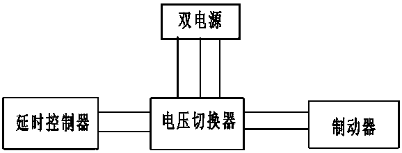
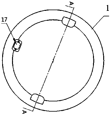
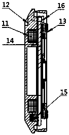
[0033] See Figure 1 to Figure 5 , the dual-power electromagnetic brake of the present invention includes a brake body 1 and a power supply module for supplying power to the brake body 1, the brake body 1 includes a yoke 12 with a coil 11 inside, a brake component 13, a brake component 13 and a yoke 12 and can cooperate with the braking component 13 to brake the component to be braked or engage and hold the armature 14 with the yoke 12, and the elastic member ...


PUM


Abstract

The invention discloses a dual-power supply electromagnetic brake, which comprises a brake body and a power supply module for supplying power for the brake body; the brake body comprises a yoke in which coils are arranged, a braking part, an armature and an elastic part, wherein the armature is located between the braking part and the yoke, and the elastic part is arranged on one face, opposite to the armature, of the yoke; the power supply module comprises a dual-power supply module, a voltage switcher and a time delay controller, wherein the dual-power supply module is capable of supplying two different voltages, the voltage switcher is electrically connected with the dual-power supply module, and the time delay controller is electrically connected with the voltage switcher; the dual-power supply module is used for supplying a high power supply to the brake body when the brake body is powered up so as to power up the coils in the brake body to pull in the armature; the time delay controller is used for sending out a switching signal to the voltage switcher after being powered up and delayed for a preset time; and the voltage switcher is used for performing switching according to the switching signal of the time delay controller to supply power for the brake body after the high power supply of the dual-power supply module is switched into a low power supply.

Description

technical field [0001] The invention relates to the field of electromagnetic brakes, in particular to a double power supply electromagnetic brake. Background technique [0002] Electromagnetic brake is an ideal automatic actuator in modern industry. It mainly plays the role of transmitting power and controlling motion in mechanical transmission system. Specifically, the electromagnetic brake is a connector that transmits the torque from the active side to the passive side. It can freely pull in and brake according to its own needs. Because it uses electromagnetic force as power, it is called an electromagnetic brake and has a fast response speed. Fast, simple structure and other advantages. The electromagnetic brake is a device that uses a energized coil to generate a magnetic field, and the magnetic field magnetizes the iron core and the armature in it. The magnetized iron core and the armature attract each other to generate electromagnetic attraction, and finally push the...

Claims


Application Information

Patent Timeline
Patent Type & Authority Patents(China)
IPC IPC(8): F16D65/18F16D121/20
CPCF16D65/18F16D2121/20
Inventor 林萍方伟陈邦力阎文龙
Owner CHONGQING HUAYU ELECTRIC GRP
Learn More