
Pipe cutting device

A technology of pipe cutting equipment and cutting platform, which is applied in metal processing and other directions, can solve the problems of waste, low cutting accuracy, time-consuming and labor-intensive, etc., and achieve the effects of avoiding waste, facilitating the cutting process, and facilitating cutting operations

Inactive Publication Date: 2016-06-29
任新庄
View PDF7 Cites 25 Cited by
  • Summary
  • Abstract
  • Description
  • Claims
  • Application Information

AI Technical Summary

Problems solved by technology

[0002] In the existing pipe processing process, the cutting of the pipe is mainly done manually, which is very time-consuming and laborious. At the same time, because the length of the pipe is mainly determined by thermal positioning during the cutting process, the cutting accuracy is not high, resulting in waste. Phenomenon

Method used


Image

  • Pipe cutting device

Examples


Embodiment 1

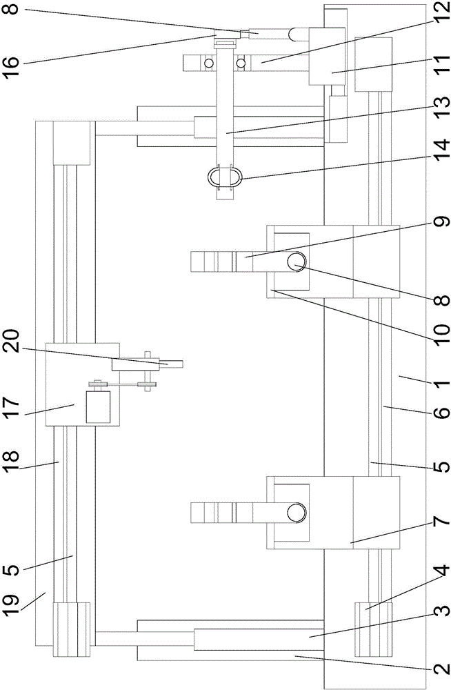
[0023] Such as figure 1 Shown, a kind of pipe material cutting equipment comprises a base 1 and a beam 19 arranged on the base, a cutting unit is arranged on the beam, a motor 4 is arranged on the base, and a motor 4 is arranged on the base. A screw 5 is arranged on the rotating shaft of the screw, a fixed shaft 6 is arranged under the screw, a tray 7 is arranged on the screw, and the tray is set on the screw and the fixed shaft. On the shaft, two hydraulic cylinders 8 facing each other are arranged on the pallet, positioning buckles 9 are respectively arranged on the telescopic rods of the two hydraulic cylinders, and the lower ends of the positioning buckles are fixedly connected to the On the hydraulic cylinder, the upper end of the positioning buckle is semicircular, and a circular structure is formed between the positioning buckles on the two hydraulic cylinders;

[0024] The cutting unit includes a cutter 20 and a motor arranged on one side of the cutter, the cutter is ...

Embodiment 2

[0028] In this embodiment, on the basis of Embodiment 1, in order to facilitate the rotation of the pipe when needed and to facilitate full cutting, preferably, a slider 11 is provided above the side of the base, and the slider 11 can be moved along the The above-mentioned base slides, a bracket 12 is arranged above the slider, and a cross bar 13 is arranged on the described bracket. One end of the bar is provided with a buckle 14, the buckle is made of sheet metal, and the middle part of the buckle is arched toward the outside of the cross bar. Move the slider so that the slider drives the bracket to move towards the direction of the pipe, so that the cross bar set on the bracket is inserted into the inside of the pipe, and the buckle set on the cross bar is snapped on the inner wall of the pipe, so that the two hydraulic cylinders on the pallet The telescopic rod shrinks, the positioning buckle moves in the opposite direction, and the cross bar is rotated so that the cross b...


PUM


Abstract

The invention discloses a pipe cutting device which comprises a base and a cross beam arranged on the base. The cross beam is provided with a cutting unit. A motor is arranged on the base. A rotating shaft of the motor is provided with a screw rod. A fixing shaft is arranged below the screw rod. A tray is arranged on the screw rod. The screw rod and the fixing shaft are sleeved with the tray. Two oppositely-arranged hydraulic cylinders are arranged on the tray. A positioning buckle is arranged on a telescopic rod of each of the two hydraulic cylinders. The lower end of each positioning buckle is fixedly connected to the corresponding hydraulic cylinder. The upper end of each positioning buckle is in a semicircular shape. A round structure is formed between the positioning buckles on the two hydraulic cylinders. The problems in the prior art can be solved, the screw rod is used for driving the tray to move to drive a pipe to move, cutting with a designated length is conveniently achieved, and meanwhile due to the adopted positioning buckle structures, the pipe can be fixed.

Description

technical field [0001] The invention relates to a pipe material cutting device. Background technique [0002] In the existing pipe processing process, the cutting of the pipe is mainly done manually, which is very time-consuming and laborious. At the same time, because the length of the pipe is mainly determined by thermal positioning during the cutting process, the cutting accuracy is not high, resulting in waste. Phenomenon. Contents of the invention [0003] The purpose of the present invention is to provide a pipe cutting device, which can improve the problems existing in the prior art. By using the lead screw to drive the pallet to move, the pipe can be driven to move, and the specified length can be cut conveniently. At the same time, the positioning buckle structure can be used to realize the pipe fixed. [0004] The present invention is realized through the following technical solutions: [0005] A pipe cutting equipment, comprising a base and a crossbeam arrang...

Claims


Application Information

Patent Timeline
Patent Type & Authority Applications(China)
IPC IPC(8): B26D1/08B26D7/01B26D7/02B26D7/06
CPCB26D1/08B26D7/01B26D7/02B26D7/0608B26D2007/013
Inventor 任新庄
Owner 任新庄
Learn More