
Multifunctional oil cylinder disassembly table

A dismantling table and multi-functional technology, applied in the direction of hand tools, manufacturing tools, etc., can solve the problems of complex structure, secondary damage of parts, difficult disassembly and assembly, etc., and achieve simple and reasonable structural design and low risk of component damage , the effect of improving labor efficiency

Active Publication Date: 2016-06-29
TIANJIN ENG MACHINERY INST
View PDF5 Cites 4 Cited by
  • Summary
  • Abstract
  • Description
  • Claims
  • Application Information

AI Technical Summary

Problems solved by technology

The dismantling process of the traditional hydraulic cylinder has great disadvantages: its dismantling efficiency is low, and there is a big problem in the dismantling process of the nut with the lever that presses the piston.
[0004] In the traditional dismantling process of hydraulic cylinders, the number of hydraulic cylinders is large, and it is difficult to disassemble and assemble with general-purpose tools, the efficiency is low, and it is easy to cause secondary damage to parts. These problems are particularly prominent
There are still several difficulties: one is that it is difficult to pull out and install the piston rod and piston assembly from the cylinder, and the other is that it is difficult to disassemble the piston lock nut.
In order to solve these two difficulties, there are many solutions in the industry, such as the method of pulling out the mechanical transmission piston rod. This method is more reliable, but due to the purely mechanical structure, the structure is very complicated
[0005] In response to these problems, it is particularly necessary to develop a new type of hydraulic cylinder dismantling table to improve efficiency and reduce the risk of damage during dismantling

Method used


Image

  • Multifunctional oil cylinder disassembly table
  • Multifunctional oil cylinder disassembly table
  • Multifunctional oil cylinder disassembly table

Examples


Embodiment Construction

[0024] In order to further understand the content of the invention, features and effects of the present invention, the following examples are given in detail as follows:

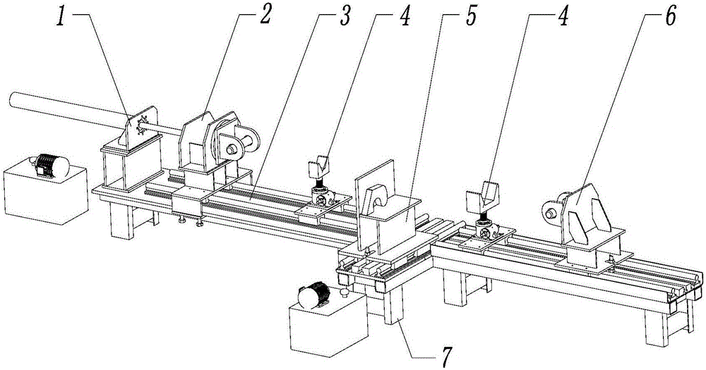
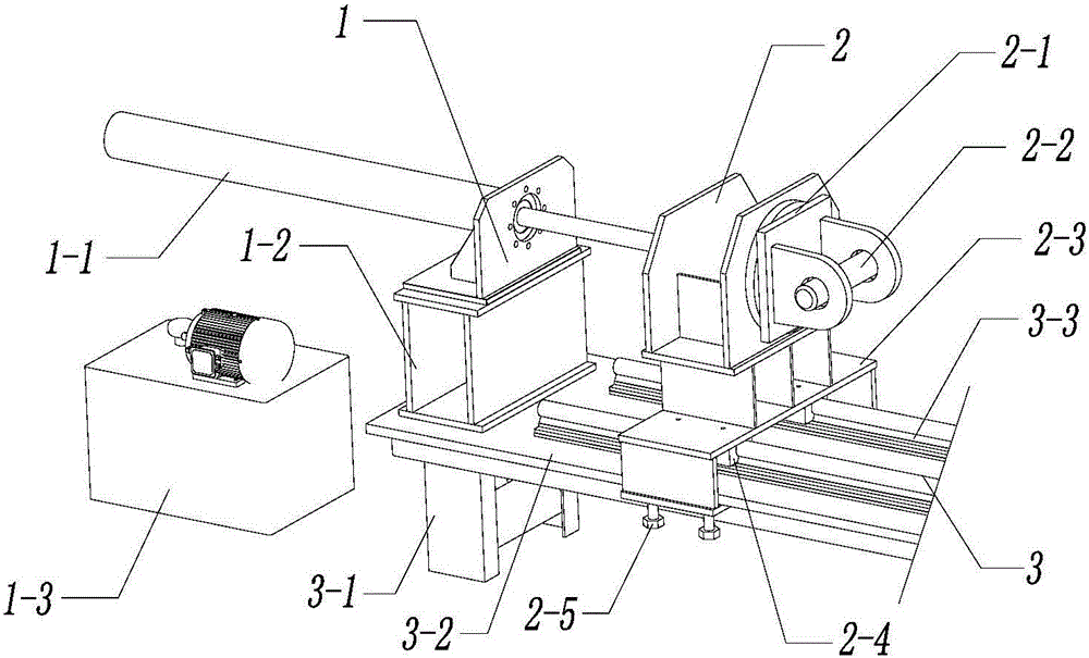
[0025] See figure 1 , the oil cylinder dismantling platform of the present invention comprises the main frame 3 that the top is fixedly installed with the first guide rail 3-3 extending along the length direction, and the side frame 7 is fixedly installed in the middle part of the main frame 3, and on the top of the side frame 7 A second guide rail 7-2 extending along the length direction is fixedly installed, and the first guide rail 3-3 and the second guide rail 7-2 are perpendicular to each other.

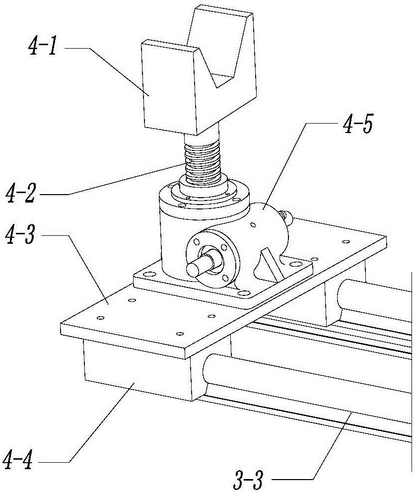
[0026] The head end of the first guide rail 3-3 is provided with a movable and fixed cylinder rod stretching device 2, and the tail end is provided with a movable and fixed cylinder barrel stretching device 6, behind the cylinder rod stretching device 2, A movable support device 4 is provided in front of the ...


PUM


Abstract

The invention relates to a multifunctional oil cylinder disassembly table. The multifunctional oil cylinder disassembly table comprises a main rack (3) fixedly provided with a first guide rail (3-3) extending along a length direction on the top, wherein a side rack (7) is fixedly installed at the middle part of the main rack (3), a second guide rail (7-2) extending along the length direction is fixedly installed at the top of the side rack (7), and the first guide rail (3-3) is perpendicular to the second guide rail (7-2); an oil cylinder rod stretching device (2) capable of moving and being fixed is arranged at the head end of the first guide rail (3-3), an oil cylinder barrel stretching device (6) capable of moving and being fixed is arranged at the tail end of the first guide rail (3-3), and support devices (4) capable of moving are arranged behind the oil cylinder rod stretching device (2) and in front of the oil cylinder barrel stretching device (6) respectively; a stretching oil cylinder device (1) for pushing and pulling the oil cylinder rod stretching device (2) to move along the first guide rail (3-3) is fixedly installed at the head end of the main rack (3); and a nut detachment device (5) capable of moving and being fixed is arranged on the second guide rail (7-2).

Description

technical field [0001] The invention belongs to the technical field of dismantling equipment, and in particular relates to a multifunctional oil cylinder dismantling platform. Background technique [0002] With the depletion of resources and the aggravation of environmental pollution, people gradually realize the importance of sustainable development, and continue to explore technical means to achieve sustainable development. Remanufacturing engineering is a new engineering discipline formed by human beings under the circumstances of increasingly scarce resources and intensified environmental pollution. It has been valued by countries all over the world because of its huge resources, environment, and social benefits. An important support for emission reduction. [0003] In the remanufacturing process of construction machinery, the first step is to disassemble the construction machinery products, then understand their damage, and then repair them according to the specific co...

Claims


Application Information

Patent Timeline
Patent Type & Authority Applications(China)
IPC IPC(8): B25B27/00
CPCB25B27/00
Inventor 李长茂张国胜陈宝庆
Owner TIANJIN ENG MACHINERY INST
Learn More