Indicator light installation structure and detection cabinet thereof

A technology of installation structure and indicator light, applied in the direction of electrical equipment shell/cabinet/drawer, printed circuit connected with non-printed electrical components, electrical components, etc., can solve electromagnetic leakage, electromagnetic shielding is ineffective, thickness is difficult to control, etc problems, to achieve the effect of simplifying product structure, simple structure and convenient operation

Inactive Publication Date: 2016-06-22
CHINA AVIATION OPTICAL-ELECTRICAL TECH CO LTD
View PDF5 Cites 2 Cited by
  • Summary
  • Abstract
  • Description
  • Claims
  • Application Information

AI Technical Summary

Problems solved by technology

In addition, due to the large number of indicator holes on the panel, it will also cause corresponding electromagnetic leakage.
[0003] At present, the main sealing measures are as follows: 1. Fill the outside of the indicator light with transparent glue to achieve sealing, but because the thickness of the panel hole glue filling is not easy to control, in order to increase the brightness of the indicator light, it needs to withstand the rubber surface, so it is usually used with better elasticity transparent silicone rubber, but the adhesive force of silicone rubber is not good, so the reliability is not high and the structure is relatively complicated, which has a certain degree of difficulty in operation. Although it is transparent rubber, it also has a weakening effect on the brightness of the indicator light. The method has no effect on the electromagnetic shielding of the chassis; 2. A shielding glass is installed on the panel, and the indicator light is placed behind the shielding glass. This method can realize electromagnetic and rain sealing at the same time, but the panel structure is more complicated and the cost is higher.

Method used


Image

  • Indicator light installation structure and detection cabinet thereof
  • Indicator light installation structure and detection cabinet thereof
  • Indicator light installation structure and detection cabinet thereof

Examples


Embodiment Construction

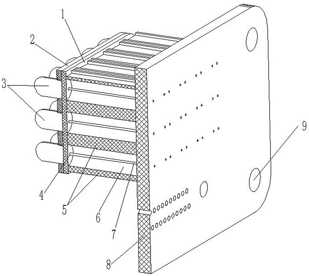
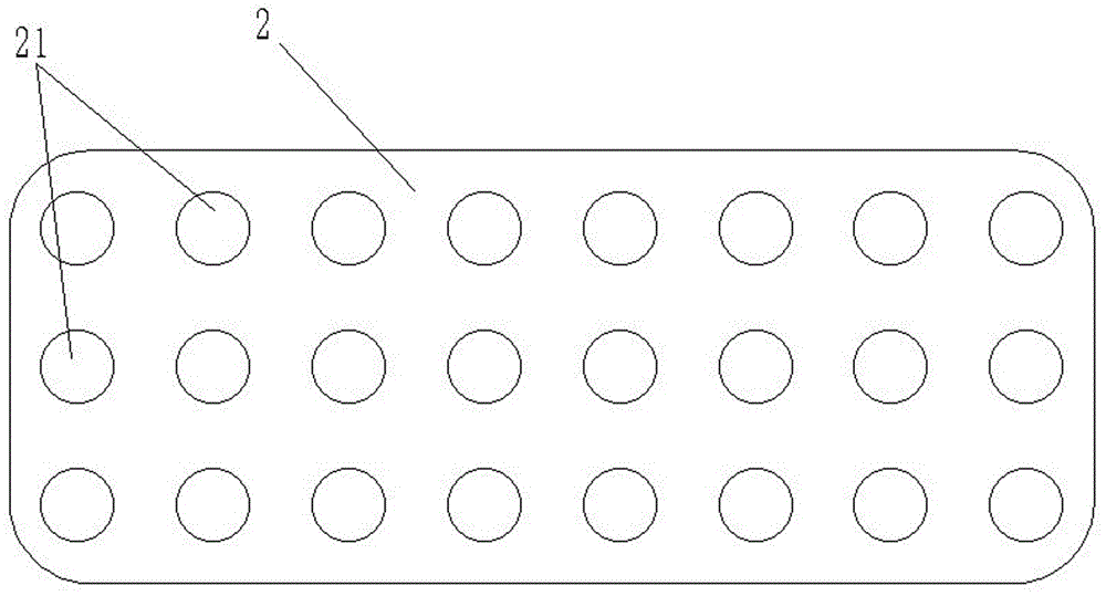
[0026] Examples of detection cabinets are Figure 1~4 As shown: it includes a panel 10, a cabinet body 3 and an indicator light installation structure. The indicator light installation structure includes a plurality of indicator lights 3 arranged on the panel and a printed board 8 arranged in the cabinet. The printed board 8 is located in the indicator light On the rear side, the indicator light 3 is a diode, and the indicator light is connected to the printed board 8 through the indicator pin 7 extending along the front and rear directions. The installation structure of the indicator light also includes a first gasket 2 made of a conductive rubber pad, the first gasket is provided with an indicator light installation hole 21 corresponding to each indicator light, and the aperture of each indicator light installation hole 21 is smaller than that of the corresponding indicator light. The outer diameter of each indicator light is installed in the corresponding indicator light in...


PUM


Abstract

The present invention relates to an indicator light installation structure and a detection cabinet thereof. The indicator light installation structure comprises an indicator light, a first sealing gasket sealed and sleeved around the indicator light and a seal gasket fixed structure configured to fix the first sealing gasket to the board of a corresponding panel and perform sealing matching of the first sealing gasket and the board of the panel. The first sealing gasket is sealed and sleeved on the indicator light, and the indicator light and the first sealing gasket are subjected to sealing matching to prevent the cabinet body from being entered by water, dust, moisture and the like through the position between the indicator light and the first sealing gasket; and the sealing gasket fixed structure is configured to fix the first sealing gasket onto the panel for ensuring the sealing between the first sealing gasket and the panel to prevent the cabinet body from being entered by water, dust, moisture and the like through the position between the panel and the first sealing gasket, so that the indicator light is thoroughly sealed. the sealing gasket structure is employed, therefore the structure is simple, the operation is convenient, and the brightness of the indicator light cannot be influenced.

Description

technical field [0001] The invention relates to an indicator light installation structure and a detection cabinet using the indicator light installation structure. Background technique [0002] As the outdoor equipment that is frequently used at present, the detection cabinet includes a cabinet body with a panel, and a printed board is arranged in the cabinet. A large number of indicator lights need to be installed on the panel. The indicator lights are connected to the printed board, and diodes are usually used as the indicator lights. When used in a moisture-proof environment such as the seaside, the indicator light needs to be sealed to prevent moisture from entering the device and corroding the electronic components and solder joints in the cabinet. In addition, because a large number of indicator holes are provided on the panel, corresponding electromagnetic leakage will also be caused. [0003] At present, the main sealing measures are as follows: 1. Fill the outside ...

Claims


Application Information

Patent Timeline
Patent Type & Authority Applications(China)
IPC IPC(8): H05K1/18H05K5/06
CPCH05K1/181H05K5/069H05K2201/10113
Inventor 陈广亮周超胡传龙程少凡王小强乔东旭高泽雄刘朋
Owner CHINA AVIATION OPTICAL-ELECTRICAL TECH CO LTD
Why Eureka
Try Eureka