Internal pressurizing testing machine

A testing machine and internal pressurization technology, which is applied in the direction of fluid tightness testing, machine/structural component testing, measuring devices, etc. The process is smooth and efficient, the overall structure is reasonable, and the action continuity is good

Active Publication Date: 2016-06-22
徐州博创建设发展集团有限公司
View PDF11 Cites 2 Cited by
  • Summary
  • Abstract
  • Description
  • Claims
  • Application Information

AI Technical Summary

Problems solved by technology

[0004] The above-mentioned test method has the following disadvantages: 1. The operation process is complicated, and the weight of the frame is relatively heavy. It is necessary to immerse the frame in water with the help of external equipment, and the installation of the steel-plastic conversion joint is also relatively troublesome; When the steel-plastic conversion joint is sealed and the sealing ring is placed outside the two ends of the steel-plastic conversion joint, and the hydraulic cylinder (or air cylinder) is used to clamp the two ends of the steel-plastic conversion joint for sealing, the strength of both is difficult to control. If the pressing or clamping force is not enough, the seal at the end of the steel-plastic conversion joint may not be reliable, which will affect the accuracy of the test and cause misjudgment of quality. If the pressing or clamping force is excessive, it may cause The deformation of the steel-plastic conversion joint causes the end face (pipe end) of the steel-plastic conversion joint to be uneven, which makes it impossible to form a seal between the steel-plastic conversion joint and the pressure plate, resulting in misjudgment of quality. Excessive force may also directly damage the steel-plastic conversion joint

Method used


Image

  • Internal pressurizing testing machine
  • Internal pressurizing testing machine
  • Internal pressurizing testing machine

Examples


Embodiment Construction

[0025] The present invention will be further described below in conjunction with the accompanying drawings and specific embodiments.

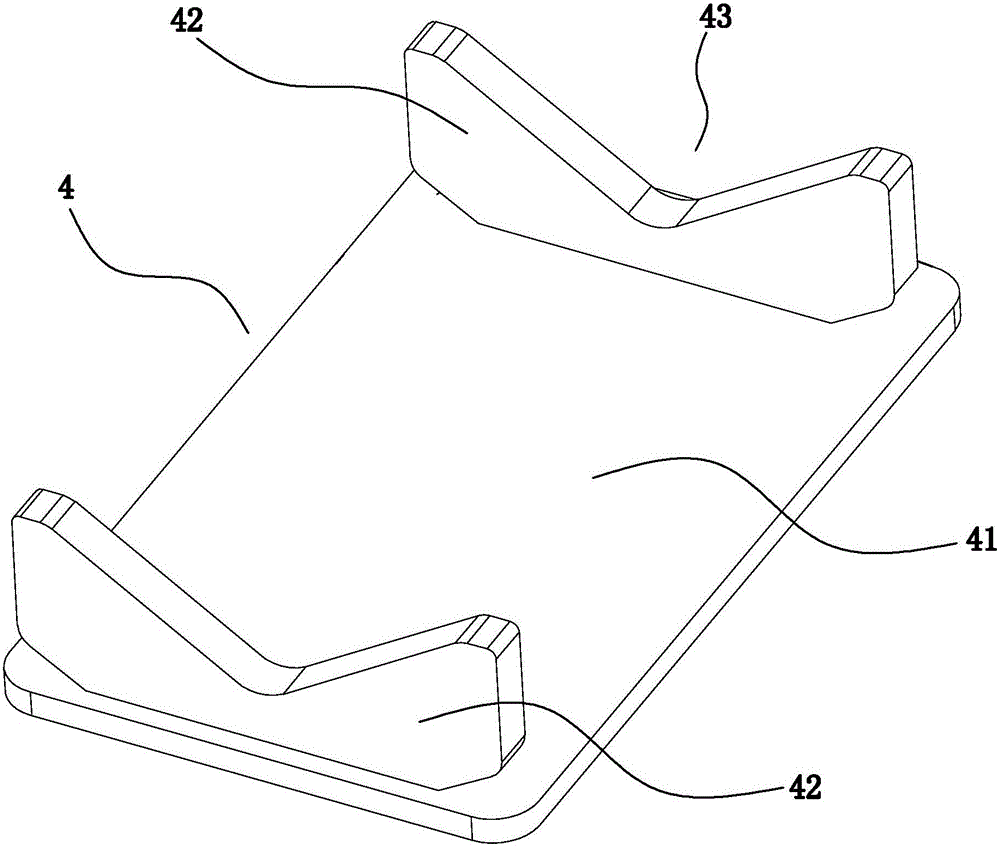
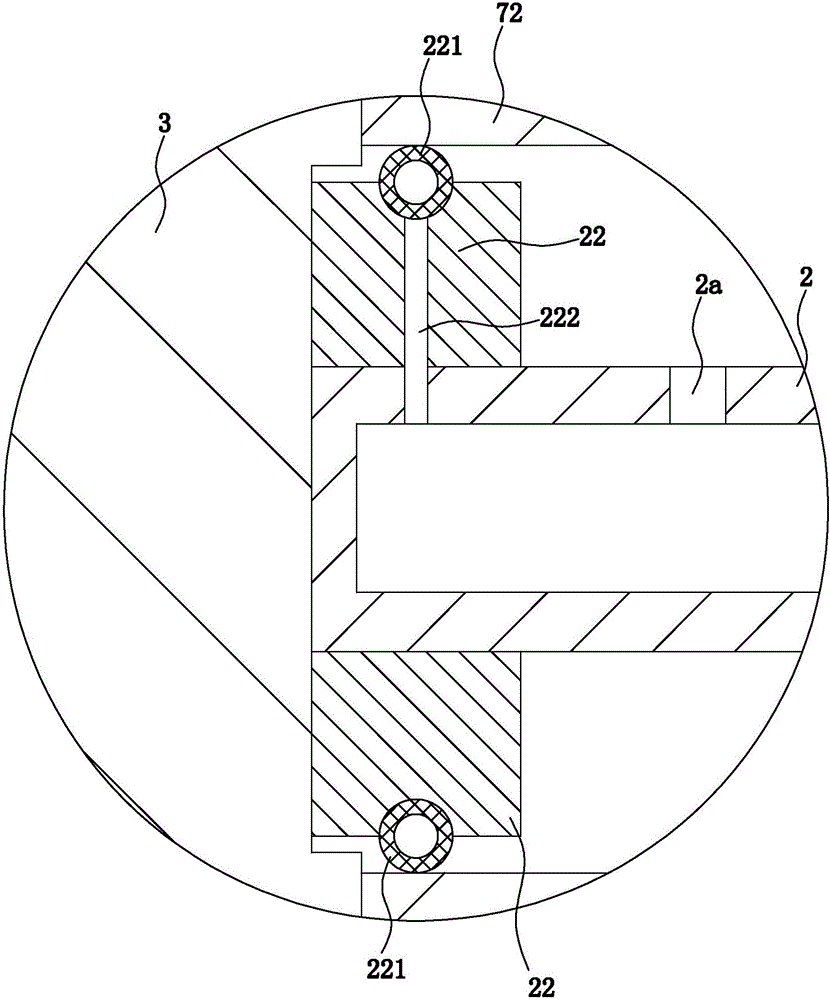
[0026] Such as Figure 1 to Figure 7 In the shown embodiment, an internal pressurization testing machine includes a main base, an air supply pump 1, a plugging cylinder, a compression cylinder, a horizontal shaft tube 2 with both ends closed, and a shaft tube 2 for contacting steel and plastic. The limit seat 3 at one end of the conversion joint, the joint support frame 4 for supporting the steel-plastic conversion joint and keeping the axis of the steel-plastic conversion joint in a horizontal state, the blocking cylinder, the compression cylinder, and the joint support frame are all set on the main base , the plugging cylinder includes a head cylinder body 51, a head cylinder piston that is sliding and sealingly matched with the head cylinder body, a head piston rod 52 connected with the head cylinder piston, the head piston rod is horizontal...


PUM


Abstract

The invention discloses an internal pressurizing testing machine which comprises a main seat, an air feeding pump, a blocking cylinder, a compaction cylinder, a shaft pipe, a spacing seat and a joint supporting rack. A compaction piston rod is provided with a positioning board. A capped piston rod is provided with a driving rack. The shaft pipe is provided with a plastic pipe outer-end sealing plate, a steel pipe outer-end sealing board, a plastic pipe outer sealing ring and a steel pipe outer-sealing ring. The shaft pipe is provided with a first air inlet. The first air inlet is provided with a first air inlet unidirectional valve. The outer wall of the shaft pipe is provided with a first air pressure sensor. A steel-plastic adapter which is supported by the joint supporting rack is arranged between the spacing seat and the blocking cylinder. The air feeding end of the air feeding pump is communicated with the inner part of the shaft pipe through an air supplying pipe. The internal pressurizing testing machine is advantageous in that reasonable integral structure is realized; in-place positioning and clamping is realized on the steel-plastic adapter; high sealing performance can be ensured without clamping damage of the steel-plastic adapter; the internal pressurizing testing machine has an adaptively adjusted sealing structure and furthermore sealing effect in high-air-pressure detection can be improved.

Description

technical field [0001] The invention belongs to the technical field of tightness testing of pipe fitting joints, and in particular relates to an internal pressurization testing machine. Background technique [0002] Steel-plastic conversion joints, also known as PE steel-plastic conversion joints, have been widely used in current production and life. For example, steel-plastic conversion joints are widely used in gas and natural gas transportation pipelines (most of the external gas pipelines are PE Pipes are mostly steel pipes when entering the room, and steel-plastic conversion joints are required during the transfer process). The steel-plastic conversion joint itself consists of a steel pipe section (a section of steel pipe) and a plastic pipe section (usually a section of PE pipe). One end of the steel pipe section is docked with one end of the plastic pipe section to form a connection section. The connection section is usually clamped by one end of the steel pipe sectio...

Claims


Application Information

Patent Timeline
Patent Type & Authority Applications(China)
IPC IPC(8): G01M3/28
CPCG01M3/2815
Inventor 宣月罗
Owner 徐州博创建设发展集团有限公司
Why Eureka
Try Eureka