
Infrared temperature-detecting device and method

A technology of infrared temperature and detection devices, which is applied in the directions of measuring devices, radiation pyrometry, measuring electricity, etc., can solve the problems of low temperature detection efficiency and poor real-time performance, achieve high real-time performance and improve the effect of collection range

Inactive Publication Date: 2016-06-22
YUNNAN POWER GRID CO LTD ELECTRIC POWER RES INST
View PDF7 Cites 9 Cited by
  • Summary
  • Abstract
  • Description
  • Claims
  • Application Information

AI Technical Summary

Problems solved by technology

[0005] An infrared temperature detection device and method are provided in the embodiment of the present invention to solve the problems of low temperature detection efficiency and poor real-time performance in the prior art

Method used


Image

  • Infrared temperature-detecting device and method
  • Infrared temperature-detecting device and method
  • Infrared temperature-detecting device and method

Examples


Embodiment 1

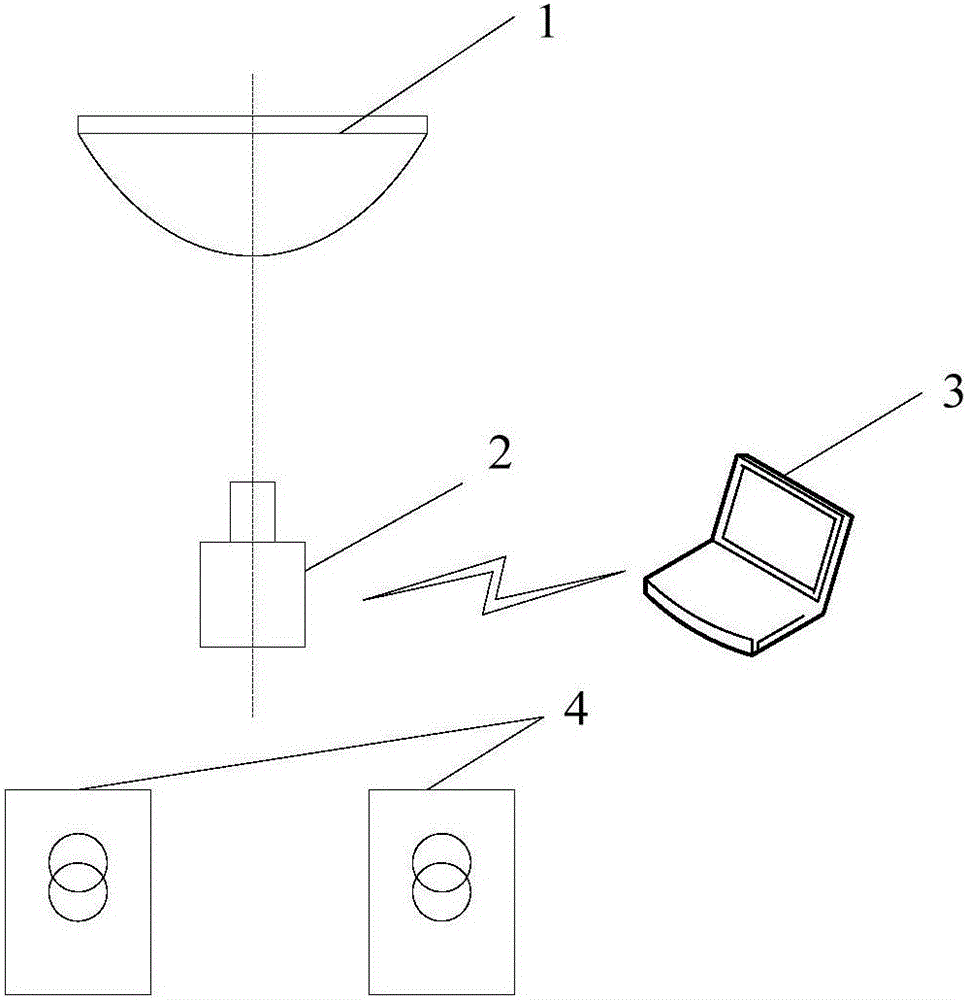
[0047] see figure 1 , is a schematic structural diagram of an infrared temperature detection device provided by an embodiment of the present invention, the infrared temperature detection device includes a convex curved mirror 1 , an infrared camera 2 and a host computer 3 .

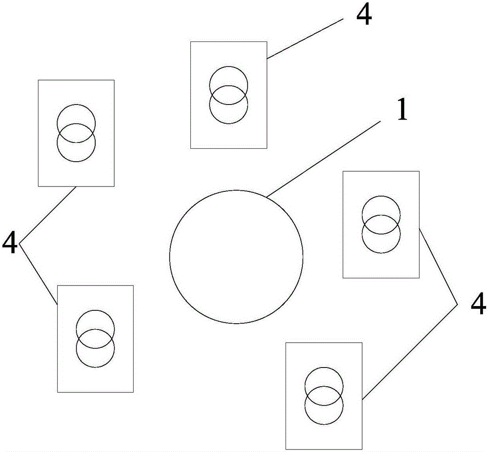
[0048] Wherein, the convex surface of the convex surface reflector 1 is provided with the electric equipment 4 to be detected; The convex curved reflector 1 may be a convex curved reflector coated with other materials or a copper convex curved reflector. The convex curved reflector 1 can collect a 360-degree panoramic view of the surrounding environment. Preferably, the convex surface of the convex curved reflector 1 includes arc-shaped, conical and parabolic convex surfaces. In the actual detection process, technicians can According to different collection environments, the convex curved reflector 1 with different convex surfaces is selected.

[0049] In order to improve the panorama acquisition effici...

Embodiment 2

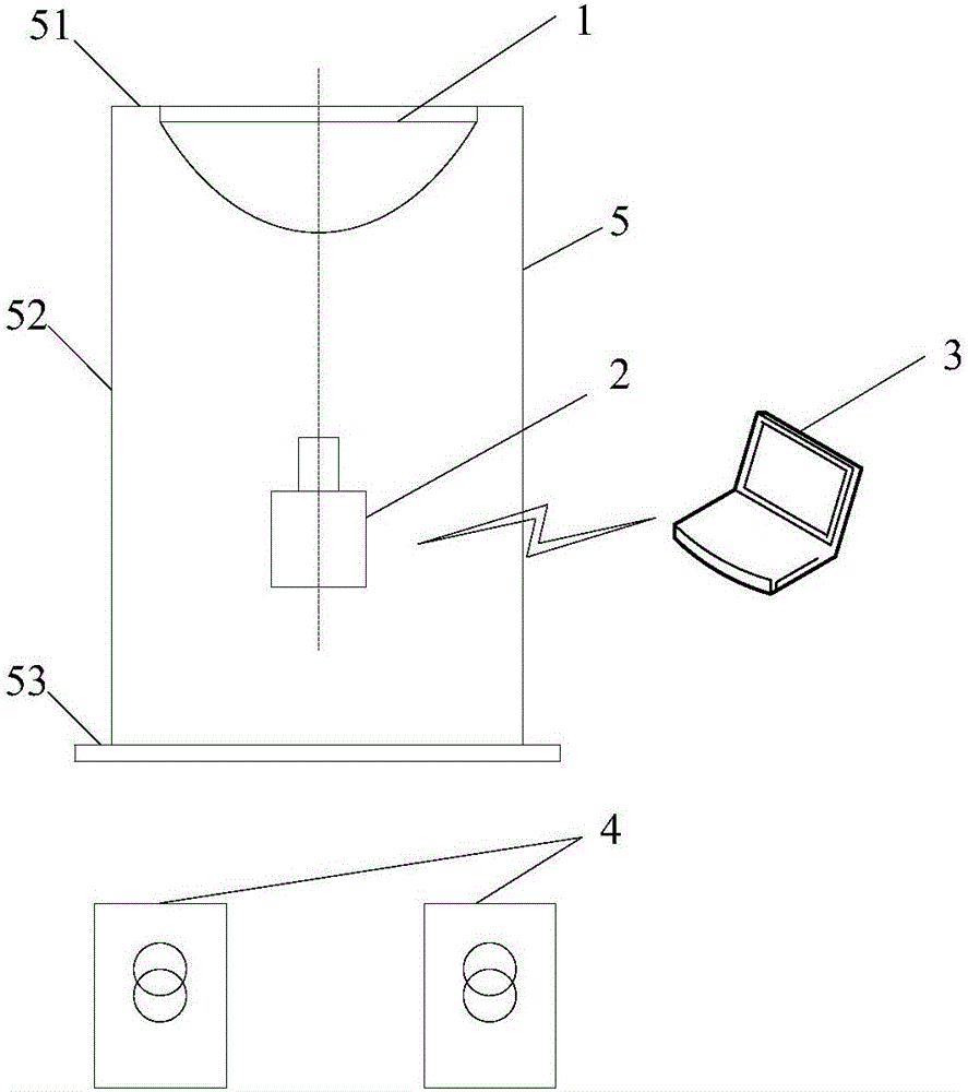
[0055] see image 3 , is a structural schematic diagram of another infrared temperature detection device provided by the embodiment of the present invention, the infrared temperature detection device includes a convex mirror reflector 1, an infrared camera 2 and a host computer 3, the difference between the embodiment of the present invention and the first embodiment The difference is that the infrared temperature detection device also includes a fixed bracket 5 . The fixing bracket 5 includes a top frame 51 , a column 52 and a base 53 .

[0056] Wherein, the top frame 51 is in fixed contact with the top surface of the convex curved mirror 1, and the top surface of the convex curved mirror 1 can be understood as a mirror surface opposite to the convex surface; the column 52 is in contact with the top frame 51 The outer edge is fixedly connected and symmetrically distributed to both sides of the convex curved mirror 1. In the embodiment of the present invention, two columns 52...


PUM


Abstract

The embodiment of the present invention discloses an infrared temperature detection device and method. By setting the convex surface of the convex surface reflector facing the electrical equipment to be detected; The mirror image on the mirror convex surface forms a mirror infrared image; the host computer is connected with the infrared camera to receive the mirror infrared image from the infrared camera and send an alarm message according to the mirror infrared image. In the actual temperature detection process, the convex curved reflector can take a 360-degree panoramic view of the surrounding environment, and can simultaneously detect the infrared temperature of multiple electrical equipment, effectively improving the range of infrared image collection and the efficiency of electrical equipment temperature detection; moreover, the upper According to the mirror infrared image collected by the infrared camera, the machine can judge whether the temperature of the power equipment is abnormal in real time. Once an abnormality occurs, it will immediately send an alarm message to notify the technicians to deal with it quickly, with high real-time performance.

Description

technical field [0001] The invention relates to the technical field of electric equipment detection, in particular to an infrared temperature detection device and method. Background technique [0002] Infrared thermal imaging uses photoelectric technology to detect infrared specific band signals of thermal radiation of objects, converts the signals into images and graphics that can be distinguished by human vision, and can further calculate the temperature value. It has the characteristics of no scanning mechanism and no need to adjust the focus to form clear images of far and near scene targets. This technology can not only be used in many fields such as safety detection, target search and tracking, and visual imaging, but also suitable for demanding environments such as high vibration and shock. Application place. [0003] In the process of power equipment fault detection, for directly visible equipment, infrared thermal imaging equipment can directly determine the therma...

Claims


Application Information

Patent Timeline
IPC IPC(8): G01J5/00G01R31/00
CPCG01J5/0096G01R31/00
Inventor 于虹
Owner YUNNAN POWER GRID CO LTD ELECTRIC POWER RES INST
Learn More