
An anti-vortex device for a pump station

A vortex and pumping station technology, which is applied to parts, pumps, and pump elements of pumping devices used for elastic fluids, can solve the problem of reducing the service life and operating efficiency of pumping stations, threatening the reliability of pumping stations, and vibration of pumping stations and noise, to improve safety, reliability and operating efficiency, reduce horizontal impact force, and suppress vortex

Inactive Publication Date: 2019-01-08
JIANGSU UNIV
View PDF6 Cites 0 Cited by
  • Summary
  • Abstract
  • Description
  • Claims
  • Application Information

AI Technical Summary

Problems solved by technology

The generation of the vortex is likely to cause vibration and noise of the pump station, and cavitation is prone to occur during long-term operation, which threatens the operational reliability of the pump station and reduces the service life and operating efficiency of the pump station.
[0003] At present, there are few domestic literature reports on the anti-vortex device of the pumping station. Patent 201310279861.3 proposes to add energy dissipation devices and deflectors in the prefabricated pumping station, so that the fluid flow state entering the suction port of the submersible pump is uniform, and the generation of vortex and vortex is prevented. Bring in air to improve the operation stability of the pump; patent 201210013684.X proposes a device for preventing vortex generation for steelmaking technology and high-efficiency continuous casting technology, but it still cannot solve the problem caused by vortex well for traditional pumping stations series of questions

Method used


Image

  • An anti-vortex device for a pump station
  • An anti-vortex device for a pump station

Examples


Embodiment Construction

[0024] The present invention will be further described below in conjunction with the accompanying drawings and specific embodiments, but the protection scope of the present invention is not limited thereto.

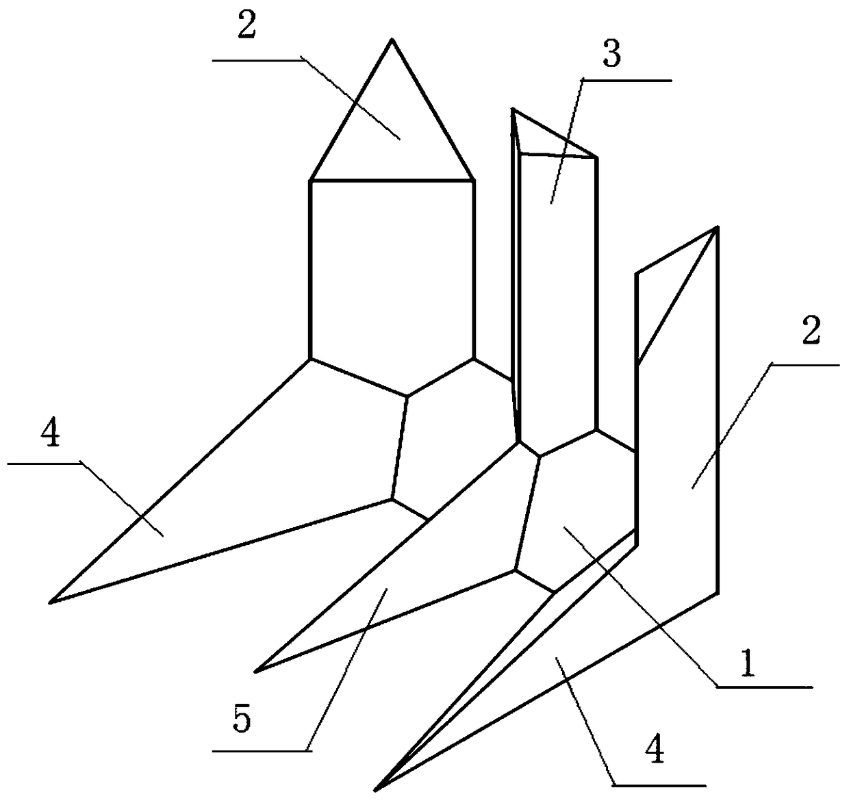
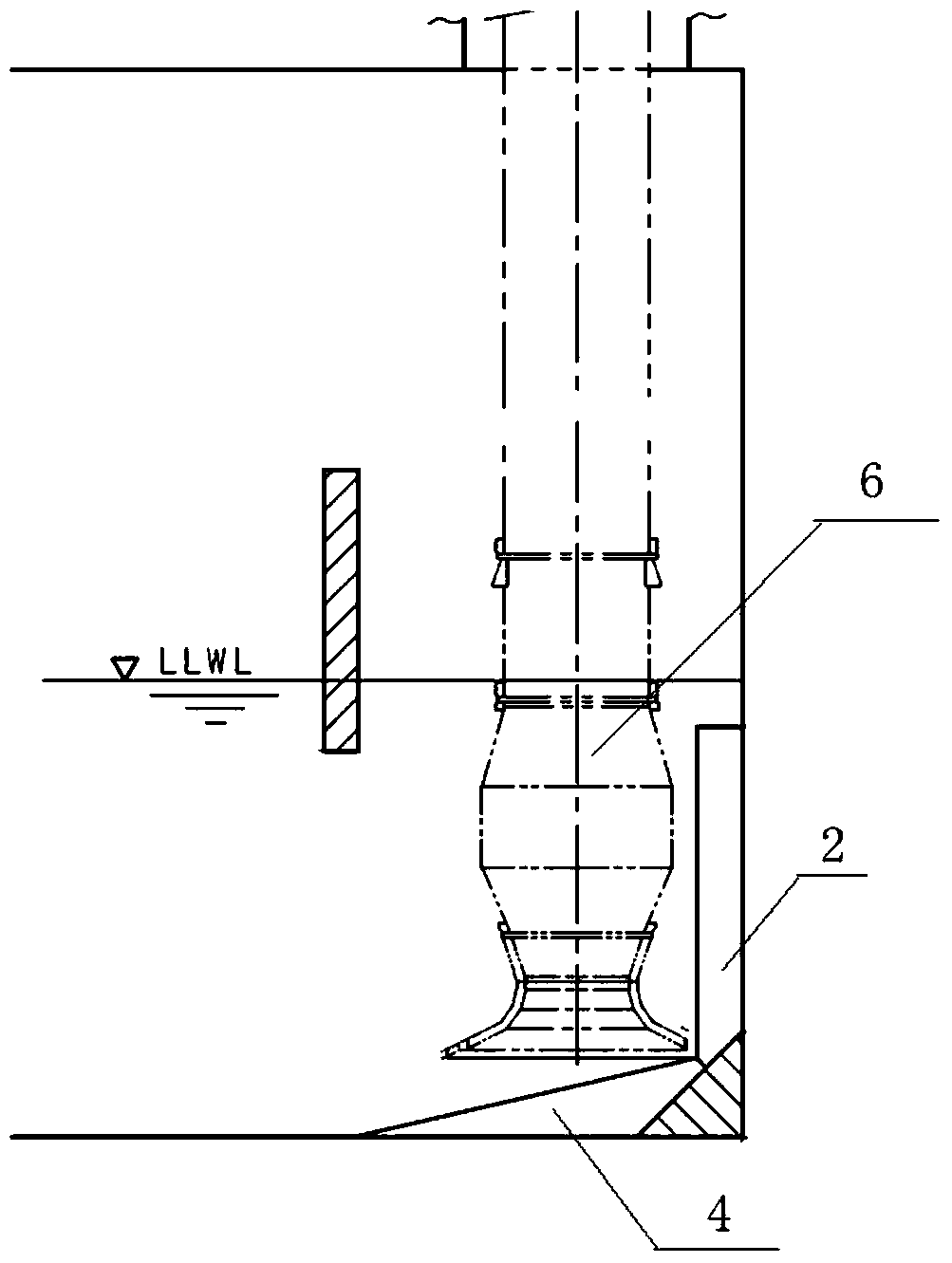
[0025] like figure 1 As shown, an anti-vortex device for a pumping station includes a straight triangular prism A1, a triangular prism B2, a triangular prism C3, a straight triangular pyramid A4 and a triangular pyramid B5; they are all welded by three stainless steel plates Made of hollow inside to save material;

[0026] Both ends of the straight triangular prism A1 are equipped with a straight triangular prism A4 horizontally, and the three form a horizontal concave structure; the bottom surface where the short edge of the straight triangular prism A4 coincides with the vertical rectangular side of the straight triangular prism A1 , the vertical right-angled side of the right triangular prism A4 coincides with the triangular base of the right triangular prism A1, the ...


PUM


Abstract

The invention provides a vortex-preventing device for a pump station. The device comprises a right triangular prism body A, right triangular prism bodies B, at least one triangular prism body C, right triangular pyramid bodies A and at least one right triangular pyramid body B, wherein the right triangular pyramid bodies A are horizontally mounted at two ends of the right triangular prism body A; the right triangular prism bodies B are vertically mounted at two ends of the right triangular prism body A; a plurality of right triangular pyramid bodies B are horizontally mounted on a part, which is located between the two right triangular pyramid bodies A, of the right triangular prism body A; the triangular prism bodies C are vertically mounted on the part, which is located between the two right triangular prism bodies B, of the right triangular prism body A, and the right triangular prism bodies B and the right triangular prism bodies C are in one-to-one correspondence. The vortex-preventing device provided by the invention can inhibit generation of vortexes well, so that the service life of the pump station is prolonged and the operating efficiency of the pump station is improved.

Description

technical field [0001] The invention belongs to the field of anti-vortex devices, in particular to an anti-vortex device for a pumping station. Background technique [0002] The traditional pump station does not add any anti-vortex device at the pump inlet. During the operation of the pump station, the water flow at the pump inlet is very turbulent. Part of the water flowing through the inlet will hit the outer wall horizontally, and part of it will be transported vertically upward along the pump. to where it is needed. The water impacting the outer wall horizontally will generate a reverse force, which mixes with the impacting force and creates a vortex at the pump inlet. The generation of the vortex is likely to cause vibration and noise of the pumping station, and cavitation is prone to occur during long-term operation, which threatens the operational reliability of the pumping station and reduces the service life and operating efficiency of the pumping station. [0003...

Claims


Application Information

Patent Timeline
Patent Type & Authority Patents(China)
IPC IPC(8): F04D29/66
CPCF04D29/669F05D2250/21F05D2250/23F05D2260/96
Inventor 张俊杰施卫东张德胜赵睿杰潘强
Owner JIANGSU UNIV
Learn More