Scissor-fork type lifting transfer machine
A technology of transfer machine and scissors, which is applied in the direction of conveyor objects, transportation and packaging, etc., can solve the problems of low transmission efficiency, low variable load bearing capacity, and impact on production beats of lifting and transfer machines, so as to reduce the failure maintenance rate , Improve variable load bearing capacity and compact structure
- Summary
- Abstract
- Description
- Claims
- Application Information
AI Technical Summary
Problems solved by technology
Method used
Image
Examples
Embodiment 1
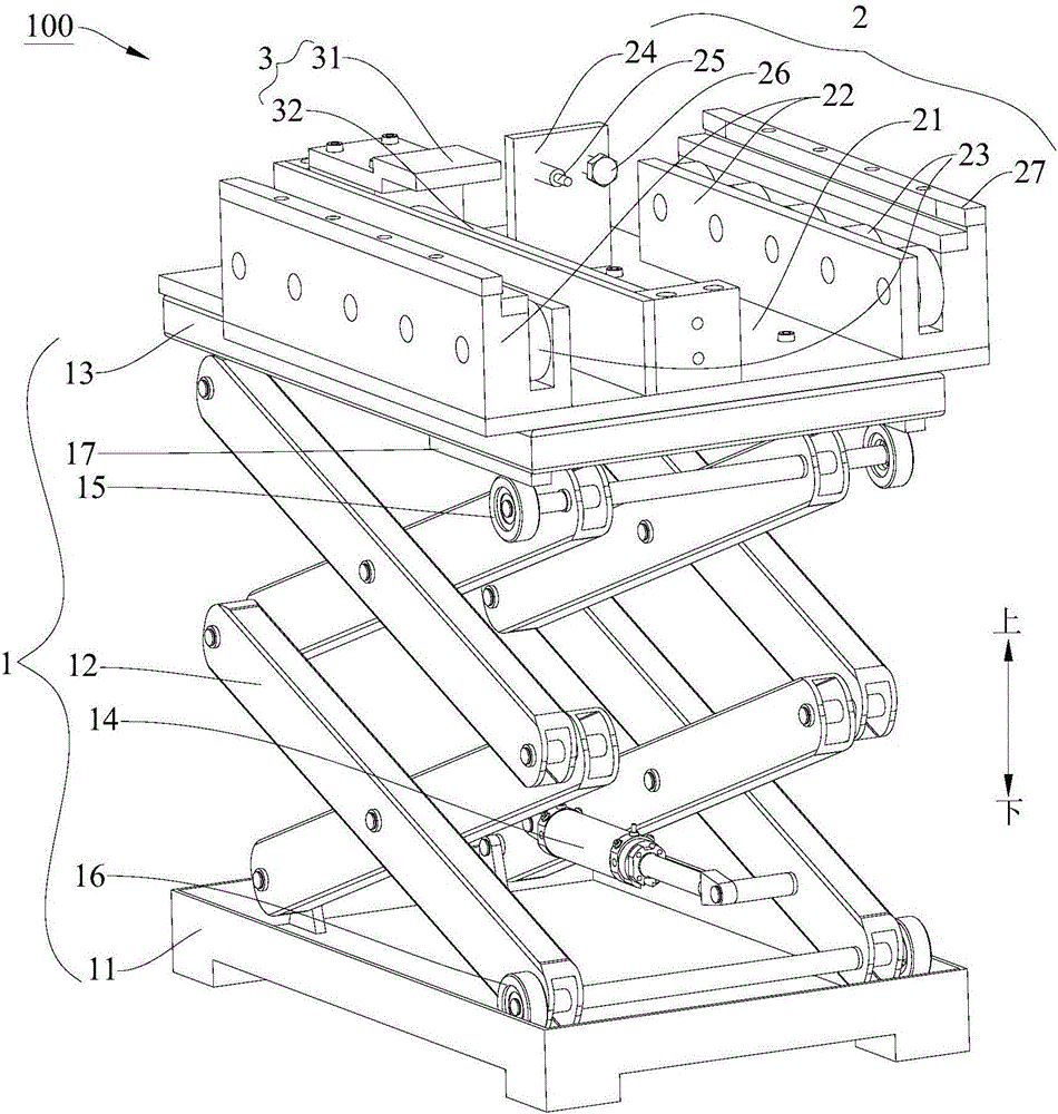
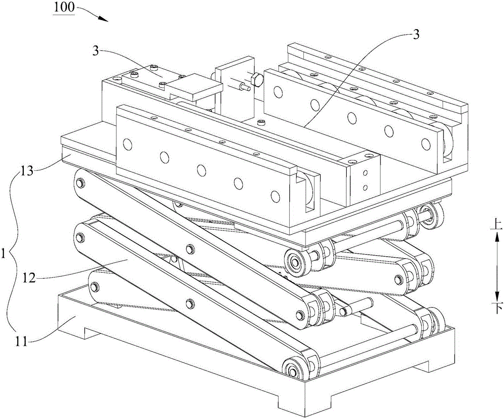
[0049] Figure 1-Figure 7 The specific structure of the scissor lift transfer machine 100 in the first embodiment is shown.
[0050] Specifically, such as Image 6 As shown, the transfer platform 2 includes: a base plate 21, a plurality of brackets 22 and multiple groups of rolling elements 23, the base plate 21 is arranged on the scissor lift frame 1, and a plurality of brackets 22 are horizontally spaced apart on the base plate 21, At least part of the upper surface of each bracket 22 defines a support surface S for placing objects. That is to say, when the article is placed on the transfer platform 2, the article is usually placed on the support surface S of the support 22, so that the article is raised by the support 22, which can prevent the article from colliding with the transfer platform 2 during the horizontal transfer process. Other parts on the board, so as to ensure the smooth transfer of items. Moreover, the article is spaced from the bottom plate 21, the conta...
Embodiment 2
[0079] Figure 8 The specific structure of the scissor lift transfer machine 100 in the second embodiment is shown, the structure of the scissor lift transfer machine 100 of the second embodiment is substantially the same as that of the scissor lift transfer machine 100 of the first embodiment, I won't go into details here.
[0080] The difference is that if Figure 8 As shown, the connection structure between the pole frame 12 and the base 11 can be different. Specific as Figure 8 As shown, the lowermost beam 120 is rotatably arranged on the base 11, and the base 11 is provided with a chute 111, and the lower end of the lowermost beam 120 is formed as a slider 123, and the slider 123 and the chute 111 Swipe to connect.
[0081] In the second embodiment, the sliding block 123 may also be provided with rollers, and the rollers fit in the chute 111 , so that the rollers roll in the chute 111 when the rod frame 12 expands or contracts.
[0082] In the second embodiment, a c...
Embodiment 3
[0084] Figure 9 The specific structure of the scissor lift transfer machine 100 in the third embodiment is shown. The structure of the scissor lift transfer machine 100 in the third embodiment is substantially the same as that of the scissor lift transfer machine 100 in the first embodiment. I won't go into details here.
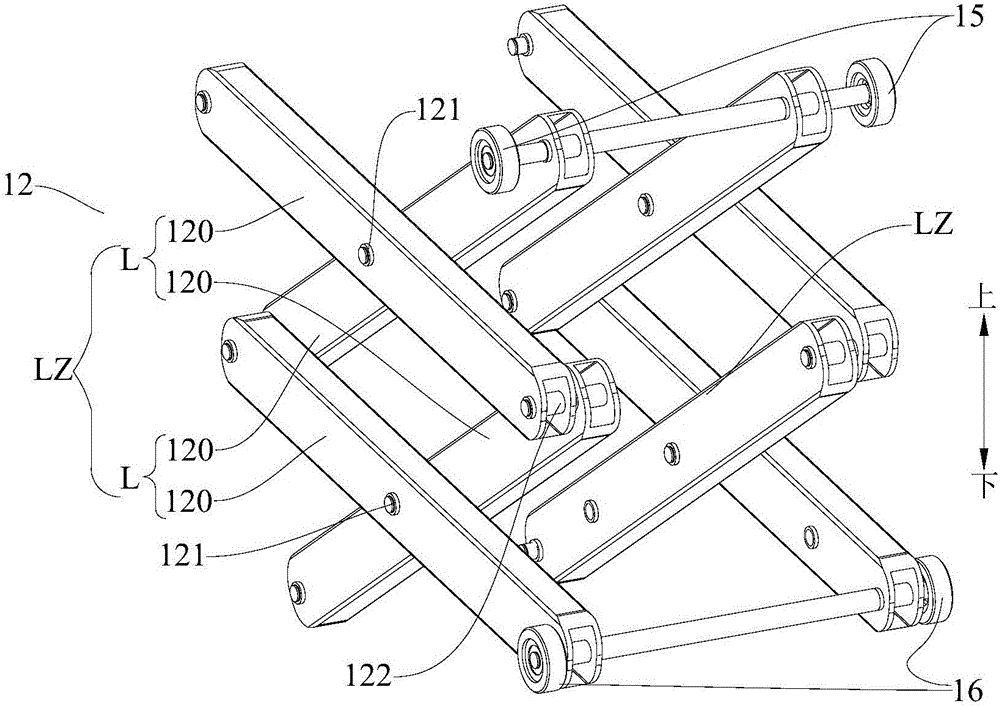
[0085] The difference is that in the third embodiment, the scissor lift frame 1 can adopt different rod frame structures. Specific as Figure 9 As shown, the rod frame 12 includes two beam chains L, and each beam chain L includes a plurality of beams 120 hingedly connected sequentially through the head and tail connecting shafts 122, and the multiple beams 120 of the two beam chains L are one by one Corresponding to the parallel arrangement, the corresponding two beams 120 in the two beam chains L form a bar layer.
[0086] In the beam chain L in the unfolded state, the lowermost beam 120 is rotatably arranged on the base 11 , and the uppermost beam 120 ...
PUM
 Abstract
Description
Claims
Application Information
 - R&D Engineer
- R&D Manager
- IP Professional
- Industry Leading Data Capabilities
- Powerful AI technology
- Patent DNA Extraction
Browse by: Latest US Patents, China's latest patents, Technical Efficacy Thesaurus, Application Domain, Technology Topic, Popular Technical Reports.
© 2024 PatSnap. All rights reserved.Legal|Privacy policy|Modern Slavery Act Transparency Statement|Sitemap|About US| Contact US: help@patsnap.com


