
Ultrasonic field auxiliary vacuum diffusion connecting device and method

A technology of vacuum diffusion and connection device, applied in welding equipment, non-electric welding equipment, metal processing equipment, etc., can solve the problems of reducing deformation resistance, strict requirements on joint surfaces, long connection time, etc., reducing deformation resistance and increasing strain. speed, effect of reducing flow stress

Active Publication Date: 2016-06-22
HARBIN PURUISI MATERIAL TECH CO LTD
View PDF6 Cites 11 Cited by
  • Summary
  • Abstract
  • Description
  • Claims
  • Application Information

AI Technical Summary

Problems solved by technology

[0005] The purpose of the present invention is to solve the problems that the existing vacuum diffusion connection method has strict requirements on the joint surface, difficult to remove the surface oxide film, long connection time and inability to reduce the connection temperature and deformation resistance, and provide an ultrasonic field assisted vacuum diffusion method. Connection device and method

Method used


Image

  • Ultrasonic field auxiliary vacuum diffusion connecting device and method
  • Ultrasonic field auxiliary vacuum diffusion connecting device and method
  • Ultrasonic field auxiliary vacuum diffusion connecting device and method

Examples


specific Embodiment approach 1

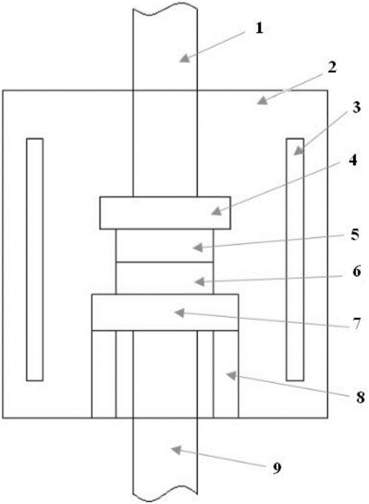
[0020] Embodiment 1: In this embodiment, an ultrasonic field-assisted vacuum diffusion connection device includes an upper pressure head 1, an upper pressure plate 4, an upper sample 5, a lower sample 6, a lower pressure plate 7, two supporting devices 8, and an ultrasonic tool head 9. Vacuum chamber 2 and heating body 3; wherein there are two heating bodies 3 on the left and right sides of the vacuum chamber 2, the lower pressing plate 7 is connected to the bottom of the vacuum chamber 2 through two supporting devices 8, and the lower pressing plate 7 is provided with an ultrasonic wave Tool head 9, lower sample 6 is placed above the lower pressing plate 7, upper sample 5 is placed above the lower sample 6, upper pressing plate 4 is provided above the upper pressing plate 4, and upper pressing head 1 is provided above the upper pressing plate 4.

specific Embodiment approach 2

[0021] Embodiment 2: This embodiment is different from Embodiment 1 in that: one or more intermediate layers can be placed between the upper sample 5 and the lower sample 6 . Others are the same as in the first embodiment.

specific Embodiment approach 3

[0022] Embodiment 3: This embodiment differs from Embodiment 1 or Embodiment 2 in that: one end of the ultrasonic tool head 9 is located inside the vacuum chamber 2 , and the other end is located outside the vacuum chamber 2 . Others are the same as in the first or second embodiment.


PUM

PropertyMeasurementUnit
Thicknessaaaaaaaaaa
Thicknessaaaaaaaaaa

Abstract

The invention relates to an ultrasonic field auxiliary vacuum diffusion connecting device and method, aims at solving the problems that according to an existing vacuum diffusion connecting method, the requirement for a joint surface is strict, a surface oxidization film is hard to remove, the connecting time is long, and connecting temperature reduction and deformation resistance reduction cannot be combined, and belongs to the technical field of diffusion connection. The device comprises an upper pressing head, an upper pressing plate, an upper sample, a lower sample, a lower pressing plate, supporting devices, an ultrasonic tool head, a vacuum chamber and a heating body. The method comprises the steps that to-be-welded base metal is cleaned; the to-be-welded base metal is assembled and placed in the vacuum chamber, the pressure is exerted, and the temperature is increased to the connecting temperature; ultrasonic vibration is exerted; and the pressure is increased, and insulating is completed. The deformation resistance of the base metal is reduced, breaking of a surface oxidization film of the base metal is accelerated, the diffusion behavior is accelerated, the connecting temperature and the connecting pressure are reduced, the connecting time is shortened, and the requirement for the surface state of the to-be-welded base metal is lowered.

Description

technical field [0001] The invention relates to an ultrasonic field assisted vacuum diffusion connection device and method. Background technique [0002] Diffusion bonding (also known as diffusion welding) refers to the surfaces of materials that are in contact with each other. Under the action of high temperature and pressure, the connected surfaces are close to each other, plastic deformation occurs locally, mutual diffusion occurs between atoms, and a new diffusion layer is formed at the interface. Thus forming a reliably connected joint. [0003] The diffusion bonding process can be roughly divided into three processes (also known as three stages) of physical contact, activation of the contact surface, diffusion and joint formation. The first stage is the physical contact stage. Under the action of external pressure on the microscopically uneven surface at high temperature, the local contact point first achieves plastic deformation. Under the action of continuous pressu...

Claims


Application Information

Patent Timeline
IPC IPC(8): B23K20/10B23K20/14B23K20/24
CPCB23K20/10B23K20/14B23K20/24
Inventor 陈晓光李大成刘丽娟彭炤宇
Owner HARBIN PURUISI MATERIAL TECH CO LTD
Learn More