High-sensitivity intensity detection method based on self-interference type micro resonator cavity light sensor

A micro-resonator, light sensor technology, applied in the field of light sensing, can solve the problems of limited measurement range, poor measurement linearity, expensive detection system, etc., and achieve the effect of reducing cost and high-precision intensity measurement

Active Publication Date: 2016-06-15
ZHEJIANG UNIV OF TECH
View PDF7 Cites 8 Cited by
  • Summary
  • Abstract
  • Description
  • Claims
  • Application Information

AI Technical Summary

Problems solved by technology

But when the measured refractive index change value is 10 -6 , the wavelength shift is only 0.35pm, requiring an expensive detection system (patent 1, ZL200810060460.8)
In the patent (patent 1, ZL200810060460.8), a method of measuring the transmission power at a certain fixed wavelength is also proposed to measure the change of the refractive index, but in fact, the frequency spectrum generated by the Fano effect is too wide. There are many problems in it, such as its limited measurement range and poor measurement linearity

Method used


Image

  • High-sensitivity intensity detection method based on self-interference type micro resonator cavity light sensor
  • High-sensitivity intensity detection method based on self-interference type micro resonator cavity light sensor
  • High-sensitivity intensity detection method based on self-interference type micro resonator cavity light sensor

Examples


example

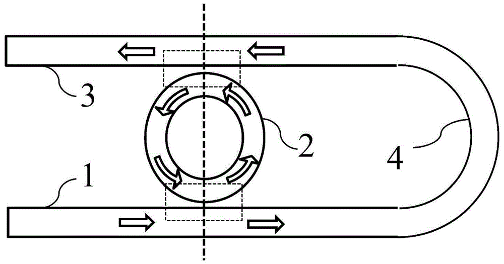
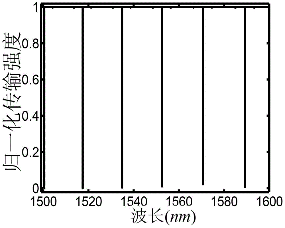
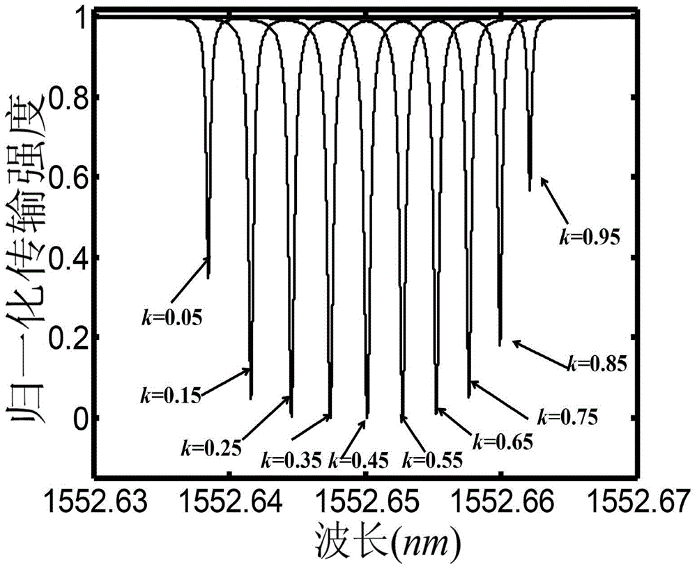
[0019] Example: In this example, the self-interference micro-ring resonant sensor, the micro-ring radius R=30μm, then the physical length L of the micro-ring circumference R =2πR, the physical length of the optical detection arm waveguide is L W =0.75L R +d. figure 2 is the emission spectrum of the self-interference microring resonator, at this time d=0.004μm, the effective refractive index n eff =2.85, the coupling coefficients of the input waveguide and the output waveguide and the microring resonator are equal to 0.5, and the loss coefficient α=0.01dB / cm per unit length of the light mode in all optical waveguides in the sensor. from figure 2 It can be seen that the emission spectrum of the self-interference microring resonator has a spectrum similar to that of a single waveguide coupled to the microring resonator, and the transmission spectrum is a spectrum with periodic distribution of transmission valleys. image 3 It shows the variation of the transmission valley a...


PUM


Abstract

The invention provides a high-sensitivity intensity detection method based on a self-interference type micro resonator cavity light sensor. An emergent frequency spectrum is similar to the frequency spectrum of a single waveguide which is coupled to the micro-ring resonator cavity, and transmission spectrum is the frequency spectrum whose transmission valley value is periodically distributed; a substance to be detected covers the upper surface of an optical detection arm waveguide, light enters from one end of an input waveguide, coupling is carried out between the light and the micro-ring resonator cavity, and one part of light is coupled into the micro-ring resonator cavity; the other part of light emits from the other end of the input waveguide and enters the output waveguide through the optical detection arm, a part of the other part of light is coupled into the micro-ring resonator cavity again due to a coupling effect between the output waveguide and the micro-ring resonator cavity, and the part of the other part of light is interfered with the part of light which is coupled by the micro-ring resonator cavity and emits from the other end of the output waveguide; change of transmission intensity at the resonance wavelength position is tested, in order to realize high sensitivity sensing. In the prerequisite that extremely high sensitivity is maintained, requirements of high-precision frequency positioning is avoided, and cost of the test system is reduced.

Description

technical field [0001] The invention relates to the technical field of light sensing, in particular to a high-sensitivity intensity detection method based on a self-interference micro-resonance cavity light sensor. Background technique [0002] In recent years, there has been a growing demand for low-cost, high-sensitivity ultra-small sensors, especially in the detection of substances such as biochemical agents and toxic gases. In response to this demand, many types of sensors have been proposed and produced in industry and academia, among which optical sensors have attracted much attention among many types of sensors due to their extremely small size and high sensitivity. Many optical phenomena, such as absorption, fluorescence, radiation, and refraction, as well as many optical media structures, such as optical fibers, photonic crystals, microring resonators, surface plasmons, and gratings, have been applied to develop new sensing mechanisms for better sensing. Good sensi...

Claims


Application Information

Patent Timeline
IPC IPC(8): G01N21/45
CPCG01N21/45G01N2021/458
Inventor 任宏亮卢瑾刘恺乐孜纯
Owner ZHEJIANG UNIV OF TECH
Why Eureka
Try Eureka