Multi-thread yarn spindle for yarn twisting machine

A twisting machine and twisting spindle technology, which is applied in the field of multifilament twisting spindles, can solve the problems of reducing the efficiency level of the twisting machine and damaging the program reliability, etc., and achieve the effects of increasing program reliability, long service life, and equal tension

Inactive Publication Date: 2016-06-15
SAURER GERMANY GMBH & CO KG
View PDF9 Cites 2 Cited by
  • Summary
  • Abstract
  • Description
  • Claims
  • Application Information

AI Technical Summary

Problems solved by technology

[0011] According to EP1726693A2, the disadvantage of this quadruple twisting spindle is that, due to the transmission ratio, the speeds of the two twisting cups running in opposite directions are always different, wherein the lower twisting cup has a higher speed and therefore turns faster
Different yarn tensions can lead to undesired thread breaks which impair program reliability and ultimately reduce the efficiency level of the twisting machine

Method used


Image

  • Multi-thread yarn spindle for yarn twisting machine
  • Multi-thread yarn spindle for yarn twisting machine

Examples


Embodiment Construction

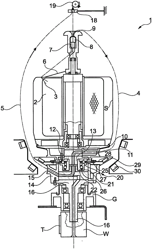
[0041] figure 1 A multifilament spindle according to the invention is shown. The yarn 3 is unwound from the package 2 and guided through the rotating flyer 6 to the braking zone 7 . After being pre-braked by the cabin-type yarn brake 8, the yarn 3 leaves the flyer 6 via the upper round head 9 and is guided to the upper twisting cup 10 around the vertical spindle disc S as an inner balloon 4.

[0042] Here the yarn 3 enters the upper yarn path 11 of the upper twisting cup 10 and is guided to the twisting cup 14 via a detour in the center of the multifilament spindle 1 . The yarn 3 is in turn deflected via the lower yarn path 15 in the lower twisting cup 14 and then guided upwards, as the outer balloon 5 , around the spindle disk S and at the same time around the inner balloon 4 .

[0043] Above the multifilament spindle 1 , the yarn 3 is now guided from the balloon yarn guide 18 to the rewinding device 19 as the yarn rotates.

[0044] During passage through the upper twistin...


PUM


Abstract

The invention relates to a multi-thread twisting spindle (1) for yarn twisting machines. The multi-thread twisting spindle includes an upper rotor (10) and a lower rotor (14), which rotate concentrically in opposite directions, wherein one of the rotors (10, 14) is driven and transmits the movement to the other rotor (10, 14) by means of a transmission device (20). According to the invention, the movement between the driven rotor (10, 14) and a transmission device output rotor (10, 14) is transmitted via at least one thrust bearing (27) and at least one radial bearing (26), wherein a cage (25) arranged in the thrust bearing (27) is present which is secured against rotation.

Description

technical field [0001] The invention relates to a multifilament twisting spindle for a twisting machine, which has an upper twisting cup and a lower twisting cup which rotate coaxially in opposite directions , where one twisting cup is driven and the motion is transmitted to the other twisting cup by means of a transmission. Background technique [0002] Twisting is a textile process used to improve yarn quality. Because a single yarn cannot meet the requirements of further processing or end products in terms of stability and uniformity, two or more yarns are twisted and entangled with each other. [0003] In this regard, there are two different ways of feeding the yarn into the twisting machine. The main yarn is wound on a feed package or in each case onto two bobbins aligned with each other. Ply yarn is, in this respect understood as a collective term for all linear fabric structures obtained by twisting yarns of the same or different kinds. The term "thread" shall inc...

Claims


Application Information

Patent Timeline
Patent Type & Authority Applications(China)
IPC IPC(8): D01H7/86F16C19/54
CPCD01H7/86F16C19/18F16C19/188F16C2340/18F16C19/545F16C19/546
Inventor 西格弗里德·布伦克因格·菲尔泽乔治·海嫩于尔根·施尼茨勒乔治·特茨拉夫
Owner SAURER GERMANY GMBH & CO KG
Why Eureka
Try Eureka