
A vertical vibration experimental device with force-controlled loading and variable layout

A vertical and layout technology, applied in the field of vertical vibration experimental devices, can solve the problems of small number of equipment, insufficiency, small working stroke, etc., to achieve low cost of construction and use, convenient installation and disassembly, and strong applicability Effect

Active Publication Date: 2016-01-13
广东空天科技研究院
View PDF8 Cites 0 Cited by
  • Summary
  • Abstract
  • Description
  • Claims
  • Application Information

AI Technical Summary

Problems solved by technology

However, the number of such experimental equipment is small, and the cost of experiments and measurements is expensive, and it is not convenient to discover new phenomena through experiments at any time during the exploratory research and development process, to carry out principle experiments, and it is not convenient to analyze the laws of some sensitive parameters and optimized design
[0005] At present, the common vertical electric vibrating table can only achieve acceleration control, but to study the vibration reduction problems of the above-mentioned engineering structures, more accurate force loading control is needed; moreover, the working stroke of the vertical electric vibrating table and other electromagnetic loading devices is generally It is not large enough to meet the requirements of the large-stroke vibration test of the structure; in addition, for some vibration damping devices, due to the special requirements for their layout, it is necessary to implement a flexible and variable layout of the experimental device in multiple ways. At present, there is no experimental device

Method used


Image

  • A vertical vibration experimental device with force-controlled loading and variable layout
  • A vertical vibration experimental device with force-controlled loading and variable layout
  • A vertical vibration experimental device with force-controlled loading and variable layout

Examples


Embodiment 1

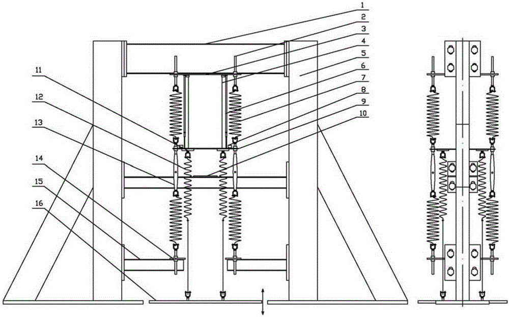
[0041] like figure 1 Shown, the structure of the present invention is as follows:

[0042]The main structure of a fixed portal steel frame is composed of two vertical supporting columns 5 and three sections of beams connected by screws, and the materials are standard I-shaped steel (25b) and steel plates. Install the top structure 3 of the fixed structure spring on the top beam 1 of the portal steel frame, and reserve the spring adjustable connection port 2 for fixed installation on it, and install two cantilever beams 15 at the bottom of the portal steel frame, A structural steel plate 14 is installed on it in a direction perpendicular to it, and an adjustable connection port 2 for fixing and installing a spring is also reserved on the steel plate 14 . These spring adjustable connection ends facilitate the adjustment of the structural spring 7 during the experiment, so that the distance between the two springs meets the specified elongation, so as to ensure the spring stiffn...

Embodiment 2

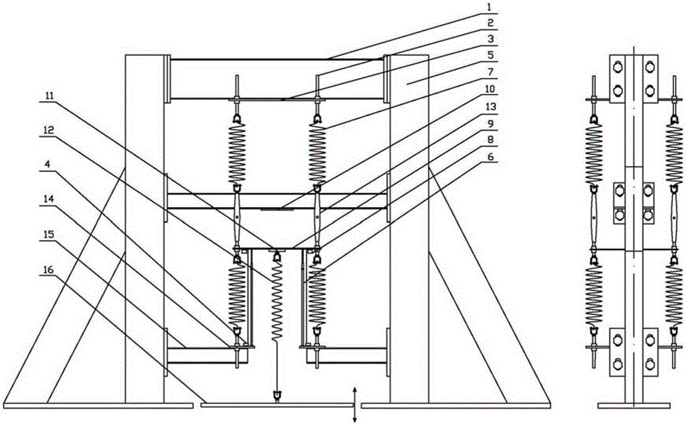
[0066] In order to meet the performance investigation of the special vibration reduction experimental device, it is sometimes necessary to install the vibration reduction experimental device on the bearing platform 10 on the upper part of the vibration structure model. For this reason, we have designed an experimental device with a different layout from Example 1, such as figure 2 shown.

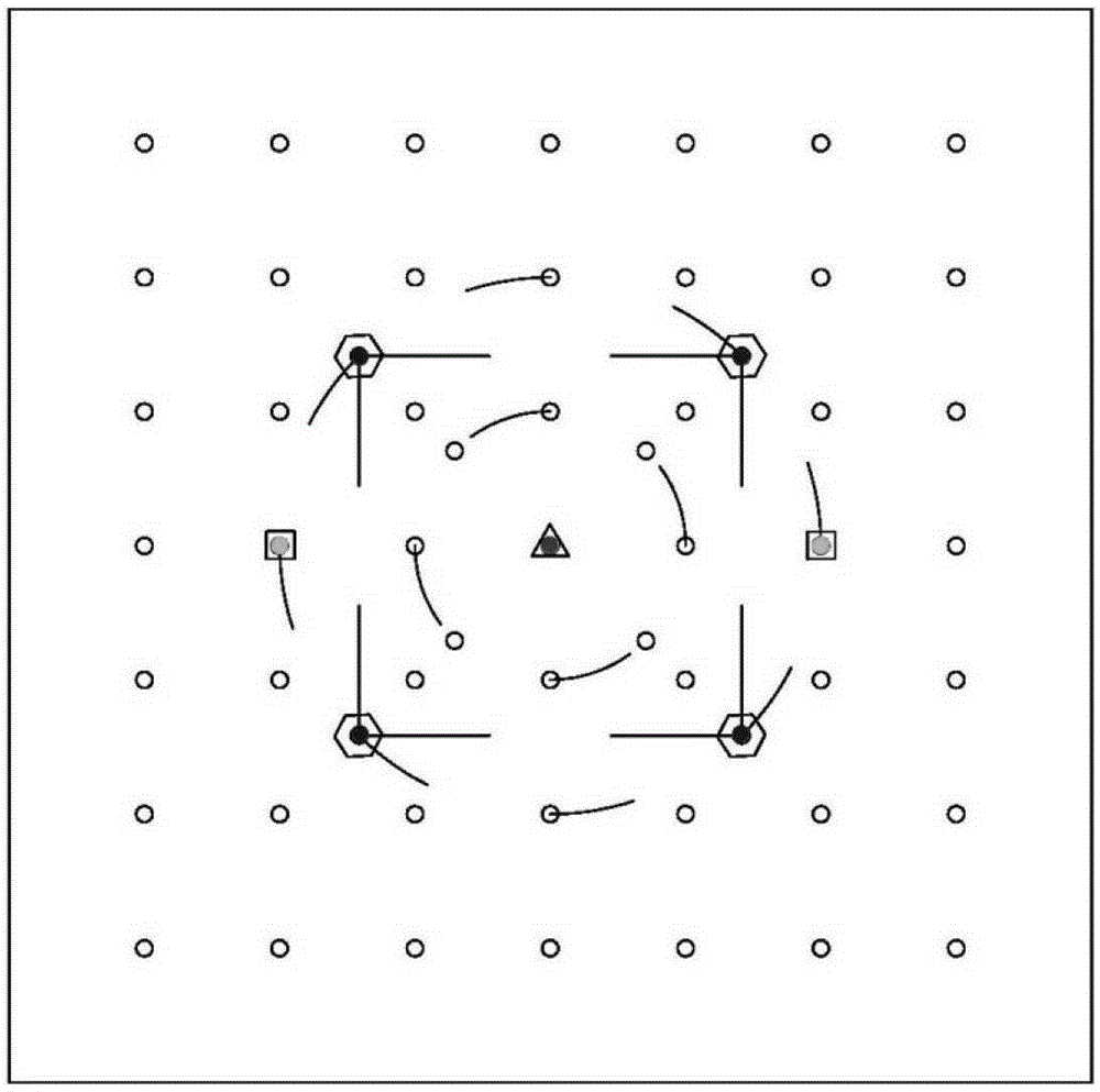
[0067] Due to the arrangement of the vibration reduction experimental device on the upper part of the vertical vibration plate 9 in this layout, it is convenient for us to implement various loading schemes on the vibration platform. Such as central single-force loading, side double-force loading, four-force loading, and even more force point loading to meet the needs of more accurate experiments to simulate real load conditions. For the layout of specific loading points, please refer to image 3 .

[0068] In the spring manufacturing process, due to the constraints of the manufacturing pr...


PUM


Abstract

The invention relates to a force control loading and layout variable vertical vibration experimental device which comprises an n-type steel frame, a vertical vibration plate, a loading spring, an acceleration sensor, a displacement sensor and an adjustable damper. The n-type steel frame comprises two supporting stand columns, a top transverse beam, a bottom transverse beam and a bearing platform, and the bearing platform is used for fixing a vibration absorber and located between the top transverse beam and the bottom transverse beam. The vertical vibration plate can be elastically and vertically arranged between the top transverse beam and the bottom transverse beam in an up-and-down vibration mode. One end of the loading spring is connected with the vertical vibration plate, the other end of the loading spring is connected with an electric vibration loading table, and the loading spring is used for exerting the predetermined external force on the vertical vibration plate. The acceleration sensor is arranged on the vertical vibration plate and used for measuring the accelerated speed of the vertical vibration plate in the vibration stress loading process. The displacement sensor is arranged between the vertical vibration plate and the top transverse beam and used for measuring the displacement value of the vertical vibration plate in the vibration stress loading process. The adjustable damper is arranged between the vertical vibration plate and the top transverse beam and used for adjusting and controlling the damping of the vertical vibration plate in the loading vibration stress loading process.

Description

technical field [0001] The invention relates to a vertical vibration experiment device with force-controlled loading and variable layout. Background technique [0002] Vibration systems are often encountered in practical engineering problems such as marine engineering structures, large-scale bridge buildings, super-long-span building structures, and aerospace satellite missile launches, machinery and instrumentation. Whether optimizing an existing system or conducting innovative research and design, experimental simulation is required. [0003] For example: at present, oil exploration is developing towards the ocean, and structures such as offshore platforms are beginning to be used more. However, these structures will produce obvious vibrations under harsh sea conditions, threatening the safety and reliability of platforms or pipelines. For large bridge buildings, when the wind load frequency is within a certain range, it will arouse a large dynamic response of the bridge...

Claims


Application Information

Patent Timeline
Patent Type & Authority Patents(China)
IPC IPC(8): G01M7/04
Inventor 曾晓辉张良余杨申仲翰
Owner 广东空天科技研究院
Learn More