
Intelligent magnetic transfer device

A transfer device and intelligent technology, applied in the direction of transportation and packaging, non-mechanical conveyors, conveyors, etc., can solve problems such as loss, workpiece slipping, collision, etc., and achieve the effect of quality assurance and reducing the probability of wear

Active Publication Date: 2017-09-29
江苏雨松环境修复研究中心有限公司
View PDF5 Cites 0 Cited by
  • Summary
  • Abstract
  • Description
  • Claims
  • Application Information

AI Technical Summary

Problems solved by technology

[0002] In the field of mechanical manufacturing and processing, workpieces are mostly completed through assembly line operations; workpieces need to go through various processes such as punching, pressing, and shaping on the assembly line. It is grasped, moved, and placed by the robotic arm, and then removed by the robotic arm and put back on the transfer track after a process is completed; due to the complex structure of the robotic arm, the robotic arm needs to twist multiple angles during the movement, so the space occupied Larger, it will cause scratches on the grasping of the workpiece at the same time; the movement range of the mechanical arm is relatively large when picking and placing, so the space reserved on each machine tool needs to be increased accordingly, which greatly increases the occupied space of the entire assembly line; In addition, when the robot arm is grabbing, it is inevitable that the workpiece will slip, collide, etc., which will cause a large loss for expensive workpieces

Method used


Image

  • Intelligent magnetic transfer device
  • Intelligent magnetic transfer device
  • Intelligent magnetic transfer device

Examples


Embodiment

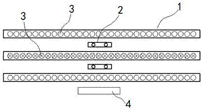
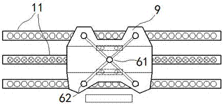
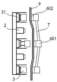
[0016] exist Figure 1 to Figure 4 In the shown embodiment, the intelligent magnetic transfer device includes a mechanical arm, a transmission track 1 and a processing machine tool 2; the transmission track 1 includes three guide rails 11 arranged in parallel, equidistant on each guide rail 11 Electromagnetic columns 3 are arranged, and the magnetic pole direction of each electromagnetic column 3 is perpendicular to the track surface of the transmission track 1; each of the electromagnetic columns 3 is electrically connected to the controller 4; when each electromagnetic column 3 is turned on, the middle one The magnetic pole direction of each electromagnetic column 3 on the guide rail 11 is opposite to the magnetic pole direction of the electromagnetic column 3 on the guide rail 11 on both sides; a lifting platform 31 is installed below each described electromagnetic column 3, and each described lifting platform 31 is coupled with the controller 4 The processing machine tool ...


PUM


Abstract

The invention relates to an intelligent magnetic motion transfer device. The intelligent magnetic motion transfer device comprises mechanical arms, a conveying track and a machining tool. The conveying track comprises three parallel guide rails. Electromagnetic columns are arranged on each guide rail at equal intervals. The electromagnetic columns are electrically connected to a controller. When the electromagnetic columns are conducted, the magnetic pole direction of the electromagnetic columns on the guide rail in the middle is opposite to the magnetic pole direction of the electromagnetic columns on the guide rails on the two sides. The mechanical arms are arranged at the two ends of the conveying track. A conveying pawl is movably arranged on each mechanical arm and comprises fixing ends and connecting rods. Each fixing end comprises an electromagnet and a suction cup located at the bottom of the electromagnet. The magnetic pole direction of the electromagnets is consistent, and the electromagnets are electrically connected with the controller. The intelligent magnetic motion transfer device is simple in structure, and the space occupied by a machining place can be effectively saved; and a large number of mechanical arm structures are simplified, the operation efficiency is effectively improved, and the operation cost is saved.

Description

technical field [0001] The present invention relates to a transfer machine, in particular, it is a magnetic transfer machine. Background technique [0002] In the field of mechanical manufacturing and processing, workpieces are mostly completed through assembly line operations; workpieces need to go through various processes such as punching, pressing, and shaping on the assembly line. It is grasped, moved, and placed by the robotic arm, and then removed by the robotic arm and put back on the transfer track after a process is completed; due to the complex structure of the robotic arm, the robotic arm needs to twist multiple angles during the movement, so the space occupied Larger, at the same time it will cause scratches on the grasping of the workpiece; the movement range of the robotic arm is relatively large when picking and placing, so the space reserved on each machine tool needs to be increased accordingly, which greatly increases the occupied space of the entire assem...

Claims


Application Information

Patent Timeline
Patent Type & Authority Patents(China)
IPC IPC(8): B65G47/91B65G54/02
CPCB65G47/91B65G54/02
Inventor 冷国强
Owner 江苏雨松环境修复研究中心有限公司
Learn More