Centralized layout electro-hydraulic power steering system for large full load passenger car
A technology of hydraulic power steering and electric steering, applied in power steering mechanism, steering mechanism, fluid steering mechanism, etc., can solve the problems of complex layout, inconvenient installation and disassembly, etc., and achieve the effect of high height, easy layout, and convenient installation and disassembly.
- Summary
- Abstract
- Description
- Claims
- Application Information
AI Technical Summary
Problems solved by technology
Method used
Image
Examples
Embodiment 1
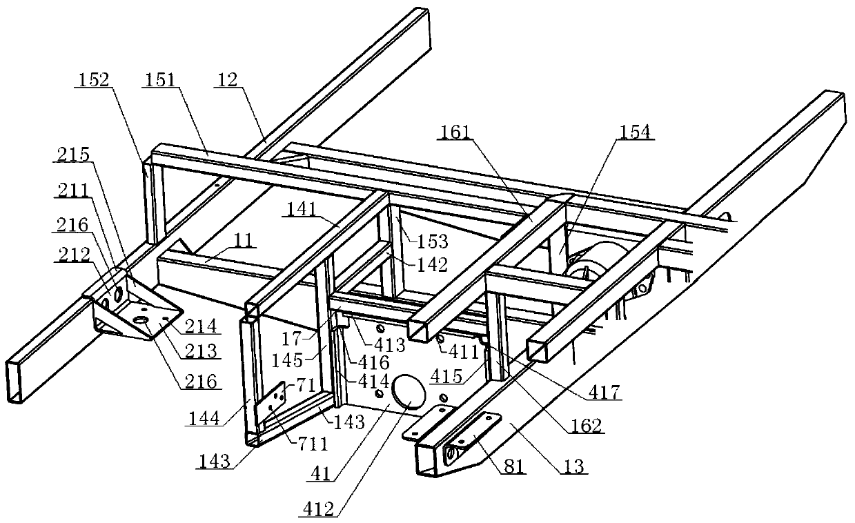
[0080] see Figure 1 to Figure 8 , a centralized layout electro-hydraulic power steering system for a large full-load passenger car, comprising a frame system 1, a steering rod system 10, and a steering pipeline system 9, the frame system 1 including a frame left longitudinal beam 11, a frame The first beam 12, the second beam 13 of the vehicle frame, the side beam frame 14 of the vehicle frame, the upper longitudinal beam frame 15 of the vehicle frame, the rear beam frame 16 of the vehicle frame, and the side longitudinal beam 17 of the vehicle frame. Commutator 2 and steering commutator bracket 21, steering intermediate transmission shaft 3, steering gear 4 and steering gear bracket 41, steering pendant arm 5, steering straight rod 6, the steering pipeline system 9 includes steering oil tank 7, electric Steering pump 8, steering gear 4, oil inlet pipeline 91, high pressure pipeline 92, low pressure pipeline 93;
[0081] The left longitudinal beam 11 of the vehicle frame is ...
Embodiment 2
[0084] Basic content is the same as embodiment 1, the difference is:
[0085] see Figure 1 to Figure 8 , the upper rail frame 15 of the frame includes an upper rail 151, a first upper rail 152, a second upper rail 154, and a third upper rail 153, and the upper rail 151 is arranged directly above the left rail 11 of the frame And parallel to the left side beam 11 of the vehicle frame, the front end of the upper cross beam 151 is vertically connected with the upper end of the first upper vertical beam 152, and the lower end of the first upper vertical beam 152 is vertically connected with the upper end surface of the first cross beam 12 of the vehicle frame. The rear end of the crossbeam 151 is vertically connected with the upper end of the second upper vertical beam 154, and the lower end of the second upper vertical beam 154 is vertically connected with the upper end surface of the second crossbeam 13 of the vehicle frame. Between the upper crossbeam 151 and the left longitud...
Embodiment 3
[0090] Basic content is the same as embodiment 1, the difference is:
[0091] see Figure 1 to Figure 8 , the steering gear bracket 41 is parallel to the left longitudinal beam 11 of the vehicle frame, the steering gear bracket 41 is provided with a steering gear installation hole 411 for installing the steering gear 4, and a steering gear output shaft through hole 412, and the steering gear 4 is connected to the steering gear through a bolt. The steering gear mounting hole 411 is connected, and the output shaft 42 of the steering gear 4 is connected with the lower end of the steering drop arm 5 after passing through the hole 412 of the steering gear output shaft; the upper end of the steering gear bracket 41 is provided with an upper bending edge 413 , the front end is provided with a front bending edge 414, the rear end is provided with a rear bending edge 415, the upper bending edge 413 is welded to the lower end surface of the frame side longitudinal beam 17, the front ben...
PUM
 Abstract
Description
Claims
Application Information
 - R&D
- Intellectual Property
- Life Sciences
- Materials
- Tech Scout
- Unparalleled Data Quality
- Higher Quality Content
- 60% Fewer Hallucinations
Browse by: Latest US Patents, China's latest patents, Technical Efficacy Thesaurus, Application Domain, Technology Topic, Popular Technical Reports.
© 2025 PatSnap. All rights reserved.Legal|Privacy policy|Modern Slavery Act Transparency Statement|Sitemap|About US| Contact US: help@patsnap.com


