Device and method for mounting plunger pump

A plunger pump and plunger rod technology, which is applied to assembly machines, metal processing equipment, manufacturing tools, etc., can solve the problems of poor sealing effect of plunger pumps, uneven force on plunger rods, and reduced service life. Effects of reduced oil leakage, easy operation, and extended service life

Active Publication Date: 2016-06-15
广州华臻机械设备有限公司
View PDF5 Cites 0 Cited by
  • Summary
  • Abstract
  • Description
  • Claims
  • Application Information

AI Technical Summary

Problems solved by technology

However, due to the low level of installation technology of the current plunger pump, the end caps on both sides of the plunger pump are prone to misalignment during the installation process, and the end caps are twisted to a certain extent, resulting in poor sealing effect of the plunger pump , there is oil leakage; the plunger rod in the plunger pump is under uneven force during the working process, and the service life is greatly reduced

Method used


Image

  • Device and method for mounting plunger pump
  • Device and method for mounting plunger pump
  • Device and method for mounting plunger pump

Examples


Embodiment 1

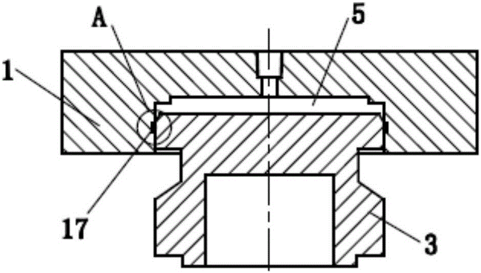
[0039] The specific embodiment of the present invention is as Figures 1 to 8 shown. A device for installing a plunger pump includes a double force cylinder 1; a pressing piston 3 is arranged on the double force cylinder 1; the pressing piston 3 is a piston driven by oil pressure.

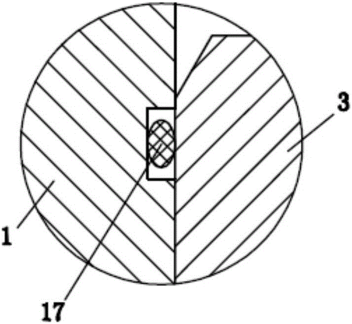
[0040] A cavity 5 is provided on the double force cylinder 1 , and one end of the compression piston 3 is located in the cavity 5 . An annular groove is provided on the side wall of the cavity 5, and a sealing ring 17 is installed on the groove. The sealing ring 17 is an O-ring. The sealing ring 17 is located between the compression piston 3 and the cavity 5, and plays a role in preventing the oil in the cavity 5 from leaking from the gap between the two.

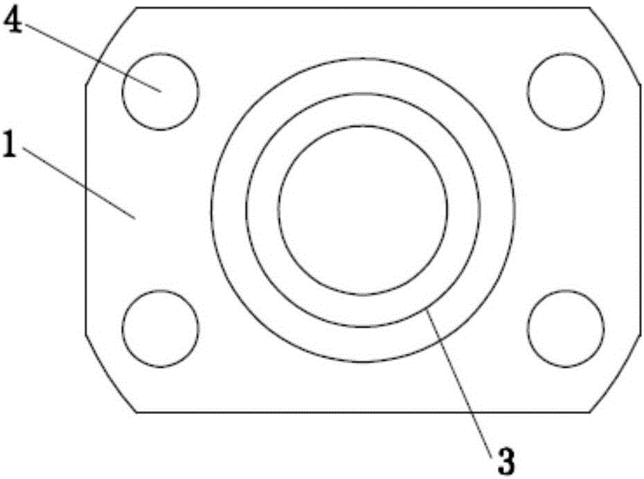
[0041] A positioning hole 4 is respectively provided at the four corners of the edge of the double power cylinder 1 . The positioning hole 4 can allow the double power cylinder 1 to be set on the four end cap screws 6 of the plunger pump. T...


PUM


Abstract

The invention discloses a device for mounting a plunger pump. The device comprises a multiplier air cylinder; a compression piston is arranged on the multiplier air cylinder, hydraulically driven and used for providing axial pressure for an end cap on the plunger pump in the mounting process. The invention further discloses a method for mounting the plunger pump, which comprises the following steps: power assembly mounting, high-pressure cylinder mounting, end cap initial mounting, multiplier air cylinder mounting, pressurizing, end cap fixing, multiplier air cylinder removing and the like. The device and the method for mounting the plunger pump, disclosed by the invention have the advantages that the method is simple; the mounting cost is lower; the situation of oblique mounting of the end cap can be reduced as much as possible, so that the oil leakage quantity is greatly reduced, and the service life of the plunger pump is prolonged.

Description

technical field [0001] The invention relates to the field of plunger pumps of water jets, in particular to a device and method for installing a plunger pump. Background technique [0002] At present, the plunger pump is the most common hydraulic drive device in water jet technology, and it is also an important part of the water jet cutting machine. Its quality directly affects the quality of water jet cutting, thereby affecting the quality of the cut product. However, due to the low level of installation technology of the current plunger pump, the end caps on both sides of the plunger pump are prone to misalignment during the installation process, and the end caps are twisted to a certain extent, resulting in poor sealing effect of the plunger pump , oil leakage occurs; the plunger rod in the plunger pump is unevenly stressed during the working process, and the service life is greatly reduced. Contents of the invention [0003] The object of the present invention is to pr...

Claims


Application Information

Patent Timeline
Patent Type & Authority Applications(China)
IPC IPC(8): B23P21/00
CPCB23P21/00
Inventor 刘振辉李岳峰吴凯倪小聪
Owner 广州华臻机械设备有限公司
Why Eureka
Try Eureka