Eureka AIR delivers breakthrough ideas for toughest innovation challenges, trusted by R&D personnel around the world.

A detector landing buffer mechanism

A buffer mechanism and detector technology, which is applied in the directions of aerospace vehicle landing devices, aircraft, motor vehicles, etc., can solve the problems of enlarged radial size and complex structure of auxiliary struts, achieve reasonable energy absorption, and reduce the workload of assembly , buffering and reliable effect

Active Publication Date: 2013-05-08
BEIJING INST OF SPACECRAFT SYST ENG
View PDF0 Cites 19 Cited by
  • Summary
  • Abstract
  • Description
  • Claims
  • Application Information

AI Technical Summary

Problems solved by technology

Aluminum honeycomb is especially suitable for cushioning compression shock loads. When the landing buffer mechanism of the Apollo manned lunar module uses it in the auxiliary pillars and buffers tensile shock loads, corresponding conversion parts are set on the structure of the auxiliary pillars. , which converts the tensile impact load into compressive impact load, thus making the structural composition of the auxiliary strut complex or the radial dimension larger

Method used


Image

  • A detector landing buffer mechanism
  • A detector landing buffer mechanism
  • A detector landing buffer mechanism

Examples


Embodiment Construction

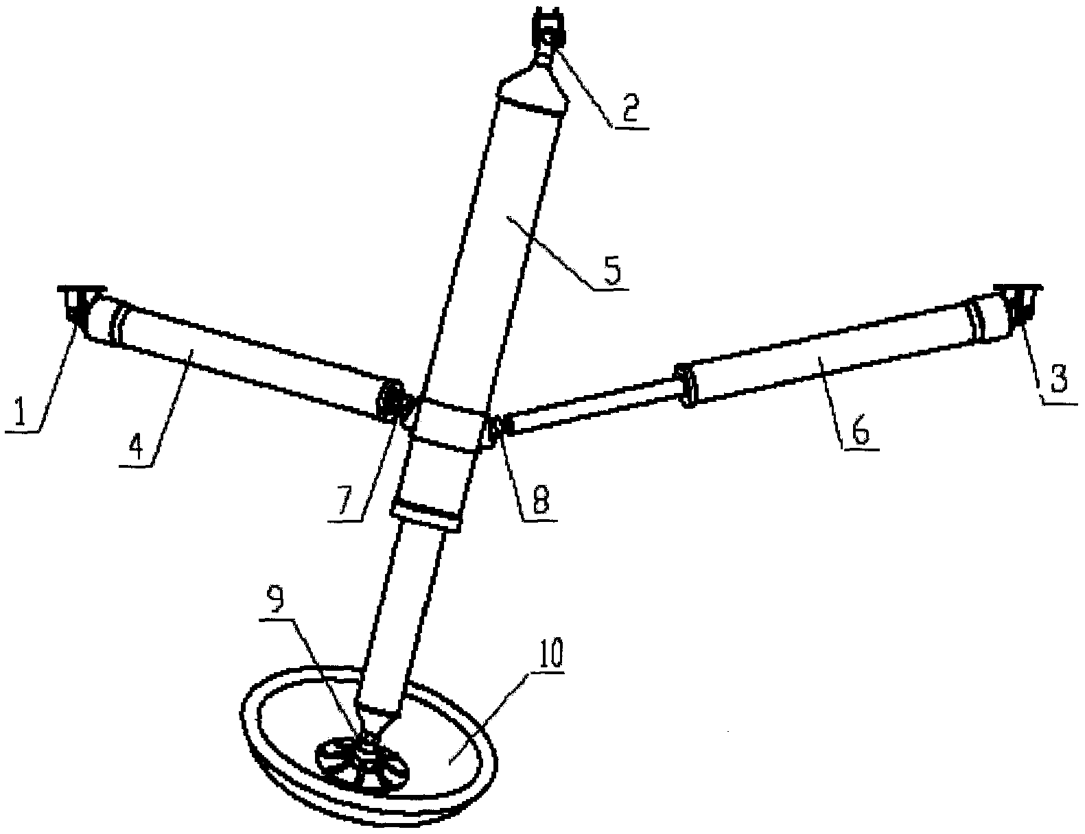
[0020] like figure 2 As shown, it is a landing buffer mechanism in a folded, compressed and folded state, which includes a main pillar 5, a multifunctional auxiliary pillar 4, a single-function auxiliary pillar 6 and a foot pad 10, and the two ends of the main pillar 5 pass through the first universal joint respectively. 2 and the first ball pair 9 are connected with the detector and the foot pad 10, and the two ends of the multifunctional auxiliary pillar 4 are respectively connected with the detector and the main pillar 5 through the second universal joint 1 and the second ball pair 7, and the single-function auxiliary The two ends of the pillar 6 are respectively connected to the detector and the main pillar 5 through the third universal joint 3 and the third ball pair 8. The main pillar 5 is a piston structure, and its interior is equipped with anti-compression impact material, which is mainly used to cushion the landing. longitudinal impact load. The multifunctional aux...


PUM


Abstract

A detector landing buffer mechanism is mainly composed of a main pillar, a multi-functional auxiliary pillar, a single-function auxiliary pillar, foot pads and the like. The multi-functional auxiliary pillar can not only buffer tensile and compressive impact loads, but also realize the functions of compression, release, deployment, and locking. There is no need to set a separate compression point when the landing buffer mechanism is assembled with the lander, which reduces the impact of the landing buffer mechanism. The interface with the landing detector is easy to install and operate. The deployment of the landing buffer mechanism is realized by the compression spring located inside the multifunctional auxiliary pillar. Even if the compression spring breaks, the deployment power will not be lost, and reliable deployment can still be guaranteed, greatly improving the reliability of deployment. In the multi-functional auxiliary pillar and the single-function auxiliary pillar, the compressive impact load is buffered through the compression deformation of the aluminum honeycomb material, and the tensile impact load is buffered through the tensile deformation of the tie rod, which not only makes the buffer more reliable, but also makes the structure simpler.

Description

technical field [0001] The invention relates to a landing buffer mechanism used for anti-shock when a probe lands on the surface of a planet. Background technique [0002] In order to ensure the safe landing of the probe on the moon or other planets, the landing buffer mechanism can be used to absorb the impact of the probe at the moment of landing, so as to ensure the safe and stable landing of the probe, thereby ensuring the safety of the instruments, equipment or personnel on the probe. , and provide long-term and effective support for the probe to work on the landing surface. The landing buffer mechanism generally consists of 3 to 4 sets of the same type of mechanism, which are evenly distributed on the bottom of the detector. Each set of landing buffer mechanism includes main pillar, auxiliary pillar, compression release device and foot pad etc. again. Corresponding cushioning materials are installed in the main pillar and the auxiliary pillar, the main pillar mainly ...

Claims


Application Information

Patent Timeline
IPC IPC(8): B64G1/62B64G1/22
Inventor 曾福明杨建中满剑锋朱汪徐青华
Owner BEIJING INST OF SPACECRAFT SYST ENG
Why Eureka
Eureka Blog
Learn More