GOA circuit, driving method and display device

A driving method and circuit technology, applied in static indicators, static memory, optics, etc., can solve the problems of abnormal display, difficulty in the characteristic curve drifting to the right, and reduce the display effect, so as to avoid abnormal display and improve the display effect. Effect

Active Publication Date: 2016-06-08
BOE TECH GRP CO LTD +1
View PDF11 Cites 7 Cited by
  • Summary
  • Abstract
  • Description
  • Claims
  • Application Information

AI Technical Summary

Problems solved by technology

[0006] Since the gate of the first transistor is connected to the first control point, when the voltage of the first control point and the voltage of the output signal terminal are equal to the first voltage, the voltage between the gate of the first transistor and the output signal terminal The difference is zero, and in a high temperature environment, abnormal display will be caused due to large leakage current, which will reduce the display effect
However, if the process makes the characteristic curve drift to the right, it is more difficult

Method used


Image

  • GOA circuit, driving method and display device
  • GOA circuit, driving method and display device
  • GOA circuit, driving method and display device

Examples


Embodiment 1

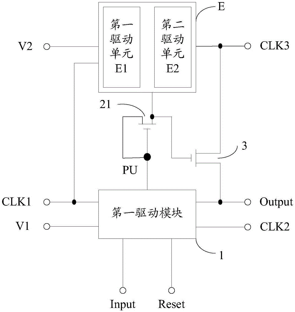
[0044] see figure 1 , the embodiment of the present invention provides a GOA circuit, including: a first driving module 1, a second driving module 2 and a first transistor 3;

[0045] The first drive module 1 is connected to the input signal terminal Input, the first clock signal terminal CLK1, the reset signal terminal Reset, the first voltage terminal V1, the second clock signal terminal CLK2, the first control point PU and the output signal terminal Output, for Under the control of the input signal of the input signal terminal Input, the voltage of the first control point PU is pulled up to a positive voltage, or the first clock signal of the first clock signal terminal CLK1, the reset signal of the reset signal terminal Reset and the second clock signal Under the control of the second clock signal at terminal CLK2, both the voltage at the first control point PU and the voltage at the signal output terminal Output are aligned with the first voltage at the first voltage term...

Embodiment 2

[0086] see Figure 5 , an embodiment of the present invention provides a driving method for a GOA circuit, the driving method comprising:

[0087] Step 201: the first driving module pulls up the voltage of the first control point to a positive voltage under the control of the input signal at the input signal terminal.

[0088] Step 202: The second driving module pulls up the gate voltage of the first transistor to a positive voltage when the first control point is at a positive voltage, so that the first transistor is turned on and the third clock signal at the third clock signal terminal output from the signal output.

[0089] optional, see Figure 4 , in the stages T1 and T2, the first driving module pulls up the voltage of the first control point to a positive voltage, and the second driving module pulls up the gate voltage of the first transistor to a positive voltage. For the specific implementation, see Embodiment 1 Relevant content will not be described in detail her...


PUM


Abstract

The invention discloses a GOA circuit, a driving method and a display device, and belongs to the field of display. The GOA circuit comprises a first driving module, a second driving module and a first transistor; the first driving module is connected with an input signal terminal, a first clock signal terminal, a reset signal terminal, a first voltage terminal, a second clock signal terminal, a first control point and an output signal terminal; a first terminal of the first transistor is connected with a third clock signal terminal, and a second terminal of the first transistor is connected with the output signal terminal; the second driving module is connected with the first control point, a second voltage terminal, the first clock signal terminal and a grid electrode of the first transistor. By means of the GOA circuit, the driving method and the display device, abnormal display can be avoided, and the display effect can be improved.

Description

technical field [0001] The invention relates to the display field, in particular to a GOA circuit, a driving method and a display device. Background technique [0002] Liquid crystal displays are widely used in electronic products such as televisions, mobile phones, and monitors. They are composed of a matrix of pixels in both horizontal and vertical directions. When displaying, the gate driving circuit outputs driving signals to scan each pixel of the liquid crystal display row by row, and the data driving circuit inputs data signals to the pixels of each row of scanning to make the liquid crystal display display. [0003] Among them, there is currently a gate drive circuit called GOA (GateOnArray) circuit. GOA refers to a shift register device that realizes Gate (gate) drive on glass (glass) by semiconductor technology. The GOA circuit includes a drive module and a first A transistor, the driving module is connected to the first control point, the input signal terminal, t...

Claims


Application Information

Patent Timeline
IPC IPC(8): G02F1/1345G09G3/36
CPCG02F1/13454G09G3/3674G09G2310/0286G11C19/28G09G3/3677G09G2310/0289G09G2320/0214G09G3/3614G09G2300/0823G09G2310/08
Inventor 王俊伟
Owner BOE TECH GRP CO LTD
Why Eureka
Try Eureka