Hardware testing equipment of battery management system

A battery management system and hardware testing technology, applied in electronic circuit testing, measuring electricity, measuring devices, etc., can solve the problems of large error and low testing efficiency of battery management system, so as to improve accuracy, improve testing efficiency and accurate testing results. Effect

Inactive Publication Date: 2016-06-08
HEILONGJIANG UNIV
View PDF6 Cites 3 Cited by
  • Summary
  • Abstract
  • Description
  • Claims
  • Application Information

AI Technical Summary

Problems solved by technology

[0003] The purpose of the present invention is to solve the problems of low test efficiency and large error in the existing battery management system, thereby providing a hardware test device for the battery management system

Method used


Image

  • Hardware testing equipment of battery management system
  • Hardware testing equipment of battery management system

Examples


specific Embodiment approach 1

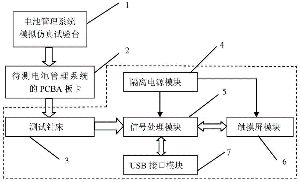
[0012] Specific implementation mode one: refer to figure 1 Describe this embodiment in detail. A battery management system hardware testing device described in this embodiment includes a test bed of needles 3, an isolated power supply module 4, a signal processing module 5, a touch screen module 6, and a USB interface module 7;

[0013] The isolated power supply module 4 provides a power supply isolated from the PCBA board 2 of the battery management system to be tested for the signal processing module 5 and the touch screen module 6,

[0014] The PCBA board 2 of the battery management system to be tested is fixed on the test needle bed 3, the test points on the PCBA board 2 of the battery management system to be tested are in close contact with the probes of the test needle bed 3, and the signal acquisition of the test needle bed 3 The wiring harness is connected to the test signal input end of the signal processing module 5, the input / output end one of the signal processing ...

specific Embodiment approach 2

[0015] Specific implementation mode two: refer to figure 2 Describe this embodiment in detail. This embodiment is a further description of a battery management system hardware testing device described in Embodiment 1. In this embodiment, the signal processing module 5 includes an interface module 5-1, a level conversion module 5-2, signal isolator 1 5-3, signal conditioning module 5-4, multi-choice one analog switch 5-5, A / D converter 5-6, signal isolator 2 5-7 and DSP 5-8;

[0016] The input end of the interface module 5-1 is the input end of the signal processing module 5, the digital signal output end of the interface module 5-1 is connected to the input end of the level conversion module 5-2, and the DSP input circuit of the level conversion module 5-2 The flat signal output terminal is connected to the input terminal of the signal isolator-5-3, the output terminal of the signal isolator-5-3 is connected to the GPIO port of the DSP5-8, and the analog signal output termina...


PUM


Abstract

The invention provides hardware testing equipment of a battery management system and belongs to the technical field of a battery management system of an electric automobile or a large-power energy storage power station, aiming at solving the problems of an existing battery management system that the testing efficiency is low and errors are great. An isolation power supply module provides an isolation power supply for a signal processing module and a touch screen module; after a PCBA (Printed Circuit Board Assembly) board card of a battery management system to be detected is fixed on a testing needle bed, and a testing point on the PCBA board card is in tight contact with a probe on the testing needle bed; a signal acquisition wiring harness of the testing needle bed is connected with a testing signal input end of the signal processing module; an input / output end I of the signal processing module is connected with the input / output end of the touch screen module; an input / output end II of the signal processing module is connected with a wiring end of a USB (Universal Serial Bus) interface, and an interface end of the USB interface module is connected with a USB interface of external equipment. With the adoption of the hardware testing equipment of the battery management system, the testing precision and the testing efficiency are improved. The hardware testing equipment is suitable for testing the battery management system.

Description

technical field [0001] The invention belongs to the technical field of battery management systems for electric vehicles or high-power energy storage power stations, and relates to a battery management system hardware testing technology. Background technique [0002] As one of the core components of the electric vehicle electronic control system, the electric vehicle battery management system has high requirements for its reliability. The electric vehicle battery management system generally consists of a main control board and a voltage acquisition board. During the production process of the main control board and the voltage acquisition board, testing the important signals and parameter indicators on the hardware PCBA board is an important means to evaluate and ensure the performance and reliability of the battery management system. At present, one is to use a multimeter, oscilloscope, etc. to test manually, but this method takes a lot of time due to the large number of sig...

Claims


Application Information

Patent Timeline
Patent Type & Authority Applications(China)
IPC IPC(8): G01R31/28
CPCG01R31/2806
Inventor 王国凤魏廷库
Owner HEILONGJIANG UNIV
Why Eureka
Try Eureka