Systems used for enabling LNG pipelines to cross over dam and construction method of systems
A pipeline and embankment technology, applied in the LNG pipeline embankment system and its construction field, to achieve the effects of reduced investment, stable structure, and easy control of construction period
- Summary
- Abstract
- Description
- Claims
- Application Information
AI Technical Summary
Problems solved by technology
Method used
Image
Examples
Embodiment 1
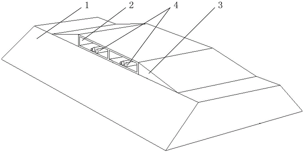
[0049] Such as figure 1 , Figure 4 and Figure 5 As shown, the LNG pipeline embankment system provided in this embodiment includes a dike 1, a box culvert 2, a slope 3, an LNG pipeline 4, an electric heating system 5, a cushion (not shown in the figure) and a waterproof layer 6, wherein , the box culvert 2 is stacked on the top of the dam 1, the slope 3 is set on both sides of the box culvert 2, and the LNG pipeline 4 passes through the dam 1 from the box culvert 2; Between the bottom plates of the box culvert 2, the waterproof layer 6 is arranged outside the box culvert 2.
[0050] In this embodiment, the dam 1 may be an earth dam, a stone dam or a concrete dam.
[0051] In this example, if Figure 6 As shown, the LNG pipeline 4 includes an inner pipe wall 41 , a heat insulating layer 42 and an outer pipe wall 43 , wherein the heat insulating layer 42 is made of a cold-insulating material.
[0052] The construction method of the LNG pipeline crossing embankment system o...
Embodiment 2
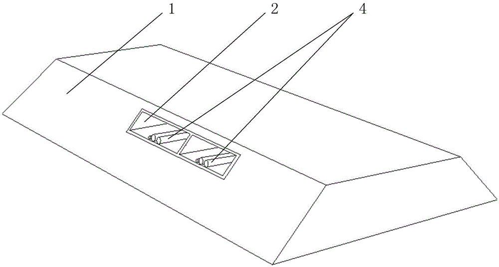
[0065] Such as figure 2 , Figure 4 and Figure 5 As shown, the LNG pipeline embankment system provided in this embodiment includes an embankment 1, a box culvert 2, an LNG pipeline 4, an electric heating system 5, a cushion (not shown in the figure) and a waterproof layer 6, wherein the box culvert 2 is set inside the embankment 1 and passes through the embankment 1, the LNG pipeline 4 passes through the embankment 1 from the box culvert 2, the electric heating system 5 and the cushion are sequentially arranged between the soil inside the embankment 1 and the bottom plate of the box culvert 2, waterproof The layer 6 is arranged outside the box culvert 2 .
[0066] In this embodiment, the dam 1 may be an earthen dam.
[0067] In this example, if Figure 6 As shown, the LNG pipeline 4 includes an inner pipe wall 41 , a heat insulating layer 42 and an outer pipe wall 43 , wherein the heat insulating layer 42 is made of a cold-insulating material.
[0068] The construction ...
Embodiment 3
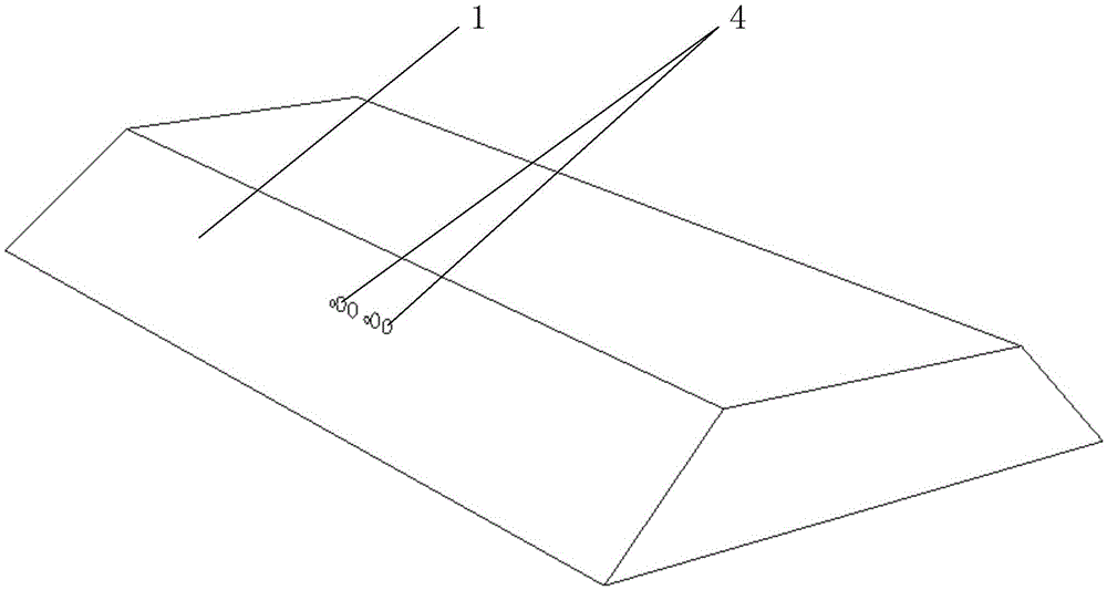
[0081] Such as image 3 and Figure 7 As shown, the LNG pipeline passing system provided in this embodiment includes a dam 1, an LNG pipeline 4 directly passing through the inside of the dam 1, and a waterproof pad 7 wrapping the outside of the LNG pipeline 4; wherein, the dam 1 can be an earthen dam; The LNG pipeline 4 includes an inner pipe wall 41, a heat insulating layer 42 and an outer pipe wall 43, the heat insulating layer 42 is made of a cold insulation material; the waterproof pad 7 can be a concrete layer or a metal material layer, and is used to reduce the water permeability of the LNG pipeline 4 .
[0082] The construction method of the LNG pipeline crossing embankment system of the present embodiment specifically comprises the following steps:
[0083] 1) Detection of the bearing capacity of embankment 1: Estimate the soil bearing capacity of each soil layer of embankment 1 after the construction of the LNG pipeline crossing embankment system. If the estimated s...
PUM
 Abstract
Description
Claims
Application Information
 - R&D Engineer
- R&D Manager
- IP Professional
- Industry Leading Data Capabilities
- Powerful AI technology
- Patent DNA Extraction
Browse by: Latest US Patents, China's latest patents, Technical Efficacy Thesaurus, Application Domain, Technology Topic, Popular Technical Reports.
© 2024 PatSnap. All rights reserved.Legal|Privacy policy|Modern Slavery Act Transparency Statement|Sitemap|About US| Contact US: help@patsnap.com


